This is an easy at home recipe that can be made in just a few hours. The most important part of the process is paying close attention to microwave timing. If your new to cheese making this is a great recipe for you. Its much tastier and better for you than cheese bought in the supermarket.
There are several recipes out there that promise 30 minute completion but I have found that with just a little more time and preparation you can greatly improve the taste and texture of your final product. As you get used to the process it becomes faster but to start take it slow and enjoy learning a new skill.
What you will need
Equipment: 1. At least an 8 quart pot either enameled or stainless steel. (Do not use aluminum, cast iron or other reactive pots) 2. Thermometer. (A candy thermometer will work but a digital thermometer is best for ease in temperature control) 3. A couple of small bowls or measuring cups to dissolve the Citric Acid and Rennet in. 4. A Large strainer to separate the Curds from the Whey. 5. A long sharp knife to cut the Curds up with. 6. A slotted spoon to stir the Curds and dip them out with. 7. Large bowl for the drained off Whey. (Glass is best) 8. Small bowl to put the Curds in. (Glass is best) 9. Microwave
Ingredients: 1. 1 gallon Milk. I use the whole milk with the red lid. Let the milk set out either in the gallon container or in the pot until it gets to about 50 degrees. If you are able to get fresh milk that is even better. you can also use alternate types of milk such as buffalo, goat , and camel just be aware that you may need to adjust salt to get the desired taste. 2. 1 Rennet tablet crushed. (The Rennet tablet is used to coagulate the milk. You can also use liquid Rennet if you can get it. You can get rennet from many cooking supply stores and specialty shops. 3. 2 teaspoons Citric Acid divided. 1 teaspoon is dissolved in water and the other one is sprinkled directly into the milk. (The citric acid is what gives the cheese it’s stretch. You can purchase this at health food stores or at most pharmacies. 4. 1/2 cup water divided in 2. (Do not use water straight form the tap use bottles,distilled ,or carbon filtered.) 5. 1 – 2 teaspoons salt.
Step One (Preparing the citric acid and rennet)
1. Pour 1 teaspoon of Citric Acid into 1/4 cup water and stir. Crush the Rennet tablet and pour it into the other cup of water. The Citric Acid should be dissolved by the time you have to use it. Most of the Rennet will be dissolved but there will still be some residue left. 2. If you haven’t done so already, pour milk into your pot. (Be sure to check milk temperature at this point it should be around 50 degrees when you pour in the Citric Acid
Step Two (Adding the citric acid)
1. Pour the dissolved Citric Acid in the milk and stir for 1 minute. 2. Now sprinkle the second teaspoon of citric acid over the milk and stir for an additional minute. At this stage you will probably see the milk begin to curdle.
Step Three (Heating the milk)
At this point you should begin to heat your milk stirring occasionally. On low heat bring the milk to a temperature of 88 to 89 degrees Fahrenheit . Using a digital thermometer of candy thermometer will ensure the proper temperature is achieved. You do not want to overheat the milk as temperatures that are too hot could pasteurize the milk. If the temperature is too low the rennet will not curdle the milk.
Step four (Adding rennet)
Once the milk mixture has reached 88-89 degrees turn off the heat and pour the rennet solution and stir gently for 20 to 30 seconds. At this point cover the pot and let sit undisturbed for twenty to thirty minutes.
Step Five (Achieving the clean break)
Once the mixture has been allowed to set you should be able to perform a clean break. (When the milk has rested long enough it becomes gel-like. At this point you can test for a break. Simply poke a clean finger (a knife may also me used) into the curd at a 45-degree angle. Lift your finger up out of the curd so the curd falls to either side. A clean break means that the curd slides off your finger in a semi-solid state with no white residue on your finger. A perfect clean break separates across your finger in a straight line. If the curd is still too liquid, it needs more time to stand undisturbed. If it is the consistency of soft yogurt, it’s almost there. Take your time as this step is very important and shouldn’t be rushed.
Step six (Cutting the curd)
Using a large sharp knife cut the curd into half inch cubes. The result should look similar to the image below.
Step Seven (Let your curds rest)
We all need to rest from time to time and you curds are no different. Once you have cut them let them sit undisturbed for 5 to 10 minutes.
Step eight ( heating your curds)
Once your curds have rested over low heat bring your mixture up to a temperature of 108 degrees Fahrenheit. Make sure to monitor temperature with a thermometer. As the curds are heated whey is expelled and the curds sink to the bottom of the pot.
Step nine (remove from heat and stir)
Once you have achieved 108 degrees Fahrenheit remove from heat and stir. Continue stirring the mixture gently off and on ( every few minutes) for approximately twenty minutes. The curds will continue to shrink as whey is expelled.
Step ten ( Separating the curds)
Using a strainer separate the curds from the whey.
Put the Curds into a strainer or colander and let set for about 15 minutes. Allow the Curds drain until no more whey comes out of them. This process might take 10 – 15 minutes. Once complete transfer curds to a small glass bowl.
Step eleven ( Heating the curds)
Its now time to use the microwave. Place the Curds in the microwave on high for 30 – 45 seconds(10 second intervals seemed to work best for me). Sorter cycles seemed to prevent overheating. The Curds will start to separate from the Whey. Depending on wattage you may need to adjust intervals.
Before heating
After heating
Step Twelve (squeeze the curd)
Using you hand or slotted spoon gently press the curds against the side of bowl to release leftover whey. Pour off whey.
Once you have poured off excess whey microwave again for 15 – 20 seconds. This time while squeezing curds work into a ball. Pour off excess whey. It should have a dough like consistency
Step Thirteen (stretching your curds)
At this point you will want to once again put the cheese into the microwave. This time heat for twenty seconds once heated mix in salt with hands. Pick up cheese as shown it should start to stretch under it’s own weight. If not put it in the microwave for a few more seconds.
Step Fourteen (knead the cheese)
At this point knead it like bread dough into a ball. If it breaks apart on you just put it in the Microwave again for a bit. As soon as it is nice and smooth and shiny it’s done. You now have some Great Home Made Mozzarella Cheese. Once finished forming ball wrap in plastic or put in a Zip lock bag and refrigerate. It can be kept in refrigerator for a week to two weeks.
This post was taken from http://www.mdpub.com/Wind_Turbine/index.htmlYou will notice that in addition to this post I posted Mike Davis`s plans for building solar panels. His were the most user friendly that I found. Since, I am not one for a lot of really complicated directions it seemed much better to have plans you can actually finish without pulling all of your hair out.
Several years ago I bought some remote property in Arizona. I am an astronomer and wanted a place to practice my hobby far away from the sky-wrecking light pollution found near cities of any real size. I found a great piece of property. The problem is, it’s so remote that there is no electric service available. That’s not really a problem. No electricity equals no light pollution. However, it would be nice to have at least a little electricity, since so much of life in the 21st century is dependent on it.
One thing I noticed right away about my property is that most of the time, the wind is blowing. Almost from the moment I bought it, I had the idea of being energy independent by putting up a wind turbine and making some electricity, and later adding some solar panels and a wood gasifier. This is the story of how I did it. Not with an expensive, store-bought turbine, but with a home-built one that cost hardly anything. If you have some fabricating skills and some electronic know-how, you can build one too.
Let me state up front that I probably won’t be able to help you out much if you decide to build your own wind turbine. This web site has become insanely popular, often taxing the bandwidth limits of the server. I get dozens of requests for help each day. I simply don’t have time to answer the majority of them. Most of the questions and requests I get are the same ones over and over again. I have created a FAQ to handle these repetitive questions. Please read it before emailing me. Simple questions, not covered by the FAQ, which only require a quick and simple answer may get replies if time permits. However, there is no way I can help you out with complex issues, teach you electronics theory, help you locate parts, build a charge controller for you, or custom design a system for you. There just aren’t enough hours in the day. Sorry.
Since no one seems to be reading the FAQ, I will answer the No. 1 question I get many, many times a day right here up front. Why didn’t I just use an automotive alternator on my wind turbine? Automotive alternators need to spin at very high speed to produce useful amounts of power. Most wind turbines don’t spin fast enough for them to work.
Update: Here is a video of the wind turbine in operation.
Update: Here is a video of me assembling and setting up the
wind turbine on my remote off-grid property.
I started the process of designing my wind turbine by Googling for information on home-built wind turbines. There are a lot of them out there in an amazing variety of designs and complexities. All of them had five things in common though:
A generator
Blades
A mounting that keeps it turned into the wind
A tower to get it up into the wind
Batteries and an electronic control system
I reduced the project to just five little systems. If attacked one at a time, the project didn’t seem too terribly difficult. I decided to start with the generator. My online research showed that a lot of people were building their own generators. That seemed a bit too complicated, at least for a first effort. Others were using surplus permanent magnet DC motors as generators in their projects. This looked like a simpler way to go. So I began looking into what motors were best for the job.
A lot of people seemed to like to use old computer tape drive motors (surplus relics from the days when computers had big reel to reel tape drives). The best apparently are a couple of models of motor made by Ametek. The best motor made by Ametek is a 99 volt DC motor that works great as a generator. Unfortunately, they are almost impossible to locate these days. There are a lot of other Ametek motors around though. A couple of their other models make decent generators and can still be found on places like Ebay. This web site talks about the virtues and vices of various Ametek motors when used as generators.
There are probably lots of other brands and models of permanent magnet DC motors available that will work well as generators. Permanent magnet DC motors work as generators, but they weren’t designed to be generators. So they aren’t great generators. Some types of motor are a lot worse than others. When used as generators, motors generally have to be driven far faster than their rated speed to produce anything near their rated voltage. So what you are looking for is a motor that is rated for high DC voltage, low rpms and high current. Steer away from low voltage and/or high rpm motors. You want a motor that will put out over 12 Volts at a fairly low rpm, and a useful level of current. So a motor rated for say 325 rpm at 30 Volts when used as a generator, could be expected to produce 12+ volts at some reasonably low rpm. On the other hand, a motor rated at 7200 rpm at 24 volts probably won’t produce 12+ volts as a generator until it is spinning many thousands of rpm, which is way too fast for a wind turbine. So shop for motors accordingly.
I managed to score one of the good 30 volt Ametek motors off of Ebay for only $26. They don’t go that cheap these days. People are catching on to the fact that they make great wind generators. Other brands will work, so don’t fret about the price Ameteks are going for. Shop wisely. Anyway, The motor I got was in good shape and worked great. Even just giving the shaft a quick turn with my fingers would light a 12 volt bulb quite brightly. I gave it a real test by chucking it up in my drill press and connecting it to a dummy load. It works great as a generator, putting out easily a couple hundred Watts with this setup. I knew then that if I could make a decent set of blades to drive it, it would produce plenty of power.
So Blades and a hub to connect them to were the next order of business. More online research ensued. A lot of people made their own blades by carving them out of wood. That looked like an outrageous amount of work to me. I found that other people were making blades by cutting sections out of PVC pipe and shaping them into airfoils. That looked a lot more promising to me. This web site tells you how to make a set of blades for a small wind turbine using PVC pipe.
I followed their general recipe. I did things a little differently though. I used black ABS pipe since my local homecenter store just happened to have pre-cut lengths of it. I used 6 inch pipe instead of 4 inch and 24 inches long instead of 19 5/8. I started by quartering a 24 inch long piece of pipe around its circumference and cutting it lengthwise into four pieces. Then I cut out one blade, and used it as a template for cutting out the others. That left me with 4 blades (3 plus one spare).
I then did a little extra smoothing and shaping using my belt sander and palm sander on the cut edges to try to make them into better airfoils. I don’t know if it’s really much of an improvement, but it didn’t seem to hurt, and the blades look really good (if I do say so myself).
Now I needed a hub to bolt the blades to and attach to the motor. Rummaging around in my workshop, I found a toothed pulley that fit on the motor shaft, but was a little too small in diameter to bolt the blades onto. I also found a scrap disk of Aluminum 5 inches in diameter and ¼ inch thick that I could bolt the blades onto, but wouldn’t attach to the motor shaft. The simple solution of course was to bolt these two pieces together to make the hub.
Much drilling, tapping and bolting later, I had a hub.
Here it is assembled and with the blades attached (after drilling mounting holes in them of course).
Here is another view of the hub with blades attached.
On a trip to the homecenter store for some PVC doo-dad or other for another project, I found these dome shaped vent caps.
I immediately thought of adding a spinner to the hub. Wow, with that on there, it really looks like a professionally made unit. I’d never be able to convince anyone I built it myself out of junk from my workshop and plumbing parts. They’d all look at me when I said I built it myself and go “Yeah, right.” Then I found a web site that claimed such spinners disrupt the airflow and hurt the efficiency of the blades. I’m not sure I believe the reasoning behind the claim, but I left the spinner off, at least initially.
Next I needed a mounting for the turbine. Keeping it simple, I opted to just strap the motor to a piece of 2 X 4 wood. The correct length of the wood was computed by the highly scientific method of picking the best looking piece of scrap 2 X 4 off my scrap wood pile and going with however long it was. I also cut a piece of 4 inch diameter PVC pipe to make a shield to go over the motor and protect it from the weather. For a tail to keep it turned into the wind, I again just used a piece of heavy sheet Aluminum I happened to have laying around. I was worried that it wouldn’t be a big enough tail, but it seems to work just fine. The turbine snaps right around into the wind every time it changes direction. For those of you always clamoring for me to provide plans, blueprints, schematics, etc., for my projects, I have added a few dimensions to the picture. I doubt any of these measurements is critical though.
Here is another view of the completed head of the unit with the motor and tail attached.
Next I had to begin thinking about some sort of tower and some sort of bearing that would allow the head to freely turn into the wind. I spent a lot of time in my local homecenter stores (Lowes and Home Depot) brainstorming. Finally, I came up with a solution that seems to work well. While brainstorming, I noticed that 1 inch diameter iron pipe is a good slip-fit inside 1 1/4 inch diameter steel EMT electrical conduit. I could use a long piece of 1 1/4 inch conduit as my tower and 1 inch pipe fittings at either end. For the head unit I attached a 1 inch iron floor flange centered 7 1/2 inches back from the generator end of the 2X4, and screwed a 10 inch long iron pipe nipple into it. The nipple would slip into the top of the piece of conduit I’d use as a tower and form a nice bearing. Wires from the generator would pass through a hole drilled in the 2X4 down the center of the pipe/conduit unit and exit at the base of the tower. Brilliant! (if I do say so myself)
For the tower base, I started by cutting a 2 foot diameter disk out of plywood. I made a U shaped assembly out of 1 inch pipe fittings. In the middle of that assembly I put a 1 1/4 inch Tee. The Tee is free to turn around the 1 inch pipe and forms a hinge that allows me to raise and lower the tower. I then added a close nipple, a 1 1/4 to 1 reducing fitting, and a 12 inch nipple. Later I added a 1 inch Tee between the reducer and the 12 inch nipple so there would be a place for the wires to exit the pipe. This is shown in a photo further down the page. I also later drilled holes in the wooden disk to allow me to use steel stakes to lock it in place on the ground.
This photo shows the head and base together. You can begin to see how it will go together. Imagine a 10 foot long piece of steel conduit connecting the two pieces. Since I was building this thing in Florida, but was going to use it in Arizona, I decided to hold off on purchasing the 10 foot piece of conduit until I got to Arizona. That meant the wind turbine would never be fully assembled and not get a proper test until I was ready to put it up in the field. That was a little scary because I wouldn’t know if the thing actually worked until I tried it in Arizona.
Next, I painted all the wooden parts with a couple of coats of white latex paint I had leftover from another project. I wanted to protect the wood from the weather. This photo also shows the lead counterweight I added to the left side of the 2X4 under the tail to balance the head.
This photo shows the finished head unit with the blades attached. Is that a thing of beauty or what? It almost looks like I know what I’m doing.
I never got a chance to properly test the unit before heading to Arizona. One windy day though, I did take the head outside and hold it high up in the air above my head into the wind just to see if the blades would spin it as well as I had hoped. Spin it they did. In a matter of a few seconds it spun up to a truly scary speed (no load on the generator), and I found myself holding onto a giant, spinning, whirligig of death, with no idea how to put it down without getting myself chopped to bits. Fortunately, I did eventually manage to turn it out of the wind and slow it down to a non-lethal speed. I won’t make that mistake again.
Now That I had all the mechanical parts sorted out, it was time to turn toward the electronic end of the project. A wind power system consists of the wind turbine, one or more batteries to store power produced by the turbine, a blocking diode to prevent power from the batteries being wasted spinning the motor/generator, a secondary load to dump power from the turbine into when the batteries are fully charged, and a charge controller to run everything.
There are lots of controllers for solar and wind power systems. Anyplace that sells alternative energy stuff will have them. There are also always lots of them for sale on Ebay . I decided to try building my own though. So it was back to Googling for information on wind turbine charge controllers. I found a lot of information, including some complete schematics, which was quite nice, and made building my own unit very easy. I based my unit on the schematic of the one found on this web site:
That web site goes into a lot of detail about the controller, so I’m only going to talk about it in fairly general terms here. Again, while I followed their general recipe, I did do some things differently. Being an avid electronics tinkerer from an early age, I have a huge stock of electronic components already on hand, so I had to buy very little to complete the controller. I substituted different components for some parts and reworked the circuit a little just so I could use parts I already had on hand. That way I had to buy almost nothing to build the controller. The only part I had to buy was the relay.
Whether you build your own, or buy one, you will need some sort of controller for your wind turbine. The general principal behind the controller is that it monitors the voltage of the battery(s) in your system and either sends power from the turbine into the batteries to recharge them, or dumps the power from the turbine into a secondary load if the batteries are fully charged (to prevent over-charging and destroying the batteries). The schematic and write-up on the above web page does a good job of explaining it.
This is a picture of the controller I built. Click on it to see a larger picture. I just bolted everything to a piece of plywood for testing purposes. Eventually I will mount it in a weather-proof enclosure.
The little perf-board in the lower center with the ICs and other bits on it is the actual controller circuit. The silver bracket below it holds two buttons that allow me to manually toggle the unit between charging batteries and dumping power to a secondary load. The big, black heat sink on the lower left has two 40 Amp blocking diodes bolted into it. I am only using one right now, but I could easily add a second wind turbine or even a photovoltaic solar panel to the system using the second one. The double row of gold rectangles across the top is a dummy load made up of high-Wattage resistors. It has taps at 2 Ohm intervals. I use it as a secondary load to dump power from the turbine into when the battery is fully charged. I also use it for testing purposes to load test the turbine. Eventually excess power from the turbine will be dumped to something more useful like a water heater or a second battery bank. Below and to the left of the dummy load is the main fuse for the wind turbine. The small gray cube is a 40 Amp SPDT automotive relay (the only part I had to purchase) which sends the turbine power either to the batteries or to the dummy load. Along the right side is the terminal block which allows me to connect everything together.
In operation, the wind turbine is connected to the controller. Lines then run from the controller to the battery. All loads are taken directly from the battery. If the battery voltage drops below 11.9 volts, the controller switches the turbine power to charging the battery. If the battery voltage rises to 14 volts, the controller switches to dumping the turbine power into the dummy load. There are trimpots to adjust the voltage levels at which the controller toggles back and forth between the two states. I chose 11.9V for the discharge point and 14V for the fully charged point based on advice from lots of different web sites on the subject of properly charging lead acid batteries. The sites all recommended slightly different voltages. I sort of averaged them and came up with my numbers. When the battery voltage is between 11.9V and 14V, the system can be switched between either charging or dumping. A pair of push buttons allow me to switch between states anytime, for testing purposes. Normally the system runs automatically. When charging the battery, the yellow LED is lit. When the battery is charged and power is being dumped to the the dummy load, the green LED is lit. This gives me some minimal feedback on what is going on with the system. I also use my multimeter to measure both battery voltage, and turbine output voltage. I will probably eventually add either panel meters, or automotive-style voltage and charge/discharge meters to the system. I’ll do that once I have it in some sort of enclosure.
I used my variable voltage bench power supply to simulate a battery in various states of charge and discharge to test and tune the controller. I could set the voltage of the power supply to 11.9V and set the trimpot for the low voltage trip point. Then I could crank the voltage up to 14V and set the trimpot for the high voltage trimpot. I had to get it set before I took it into the field because I’d have no way to tune it up out there.
Update: I am now using 14.8V for the full charge point after further researching the proper charging of lead-acid batteries. I have also switched to sealed lead-acid batteries because I got a bunch of them free from my brother. I am contemplating switching to deep-cycle batteries when the ones I have now begin to fail.
Update: I have found out the hard way that it is important with this controller design to connect the battery first, then connect the wind turbine and/or solar panels. If you connect the wind turbine first, the wild voltage swings coming from the turbine won’t be smoothed out by the load of the battery, the controller will behave erratically, the relay will click away wildly, and voltage spikes could destroy the ICs. So always connect to the battery(s) first, then connect the wind turbine. Also, make sure you disconnect the wind turbine first when taking the system apart. Disconnect the battery(s) last.
Update: Finally, by very popular demand, I have a schematic of my charge controller. Click on it for the full size schematic. It only varies a little bit from the one at the above link. I substituted a few parts I had on hand for ones in the original design. That way I only had to buy a few things to build the controller. You could do the same. It is not critical to exactly duplicate this design. I used a different op-amp chip and a different MOSFET than the original design. Most of the resistor values are not critical. If you have the knowledge to do so, feel free to substitute. Also, feel free to experiment. I’d be interested in hearing from anyone who feels they have improved on the design in any way.
At last, all parts of the project were complete. It was all done only a week before my vacation arrived. That was cutting it close. I disassembled the turbine and carefully packed the parts and the tools I’d need to assemble it for their trip across the country. Then I once again I drove out to my remote property in Arizona for a week of off-grid relaxation, but this time with hopes of having some actual electricity on the site.
The first order of business was setting up and bracing the tower. After arriving at my property and unloading my van, I drove to the nearest Home Depot (about 60 miles one way) and bought the 10 foot long piece of 1 1/4 inch conduit I needed for the tower. Once I had it, assembly went quickly. I used nylon rope to anchor the pole to four big wooden stakes driven in the ground. Turnbuckles on the lower ends of each guy-line allowed my to plumb up the tower. By releasing the line from either stake in line with the hinge at the base, I could raise and lower the tower easily. Eventually the nylon line and wooden stakes will be replaced with steel stakes and steel cables. For testing though, this arrangement worked fine.
This photo shows a closeup of how the guy-lines attach near the top of the tower. I used chain-link fence brackets as tie points for my guy-lines. The fence brackets don’t quite clamp down tightly on the conduit which is smaller in diameter than the fence posts they are normally used with. So there is a steel hose clamp at either end of the stack of brackets to keep them in place.
This photo shows the base of the tower, staked to the ground, and with the wire from the wind turbine exiting from the Tee below the conduit tower. I used an old orange extension cord with a broken plug to connect between the turbine and the controller. I simply cut both ends off and put on spade lugs. Threading the wire through the tower turned out to be easy. It was a cold morning and the cord was very stiff. I was able to just push it through the length of the conduit tower. on a warmer day I probably would have had to use a fishtape or string line to pull the cord through the conduit. I got lucky.
This photo shows the turbine head installed on top of the tower. I greased up the pipe on the bottom of the head and slid it into the top of the conduit. It made a great bearing, just as I’d planned. Sometimes I even amaze myself.
Too bad there was nobody around to get an Iwo Jima Flag Raising type picture of me raising the tower up with the head installed.
Now I’m just waiting for the wind to blow. Wouldn’t you know it, it was dead calm that morning. It was the first calm day I had ever seen out there. The wind had always been blowing every other time I had been there. Well, nothing to do but wait.
Finally! The wind was up and the turbine was spinning. The winds were actually unusually light the whole time I was on my property this time. The wind turbine still made good amounts of power though, even with winds that at best made it to only a little over 20 mph at times.
This photo shows the controller, battery and associated electronics all wired up. I have a 120V inverter connected to the battery and a multimeter to keep track of the battery voltage and wind turbine output voltage. Also my electric shaver and battery charger are plugged into the inverter and running off of 120V AC. Later I plugged a long extension cord into the inverter and stretched it back to my camp site. I know this setup is really messy, but I was in a hurry to get up and running to take advantage of the wind once it started blowing. That’s my excuse, and I’m sticking to it.
This photo is a closeup of the electronics. The meter shows that the wind turbine is producing 13.32 Volts. My electric shaver and battery charger are providing loads on the system through the AC inverter.
Here the meter shows the turbine producing 13.49 volts. The voltage from the turbine goes up only a little as the wind speed increases once it has a load to power. Once the wind starts blowing, the turbine head snaps around into it and begins spinning up. It spins up quickly until the output voltage exceeds the battery voltage plus the blocking diode drop (around 13.2 volts, depending on the state of the battery charge). it is really running without a load until that point. Once the that voltage is exceeded, the turbine suddenly has a load as it begins dumping power into the battery. Once under load, the rpms only slightly increase as the wind speed increases. More wind means more current into the battery which means more load on the generator. So the system is pretty much self-governing. I saw no signs of over-reving. Of course in storm-force winds, all bets are off. Switching the controller to dump power into the dummy load did a good job of braking the turbine and slowing it way down even in stronger gusts. Actually shorting the turbine output is an even better brake. It brings the turbine to a halt right now, even in strong winds. Shorting the output is how I made the turbine safe to raise and lower, so I wouldn’t get sliced and diced by the spinning blades. Warning though, the whole head assembly can still swing around and crack you hard on the noggin if the wind changes direction while you are working on these things. So be careful out there.
Eventually I decided my setup was too messy and dangerous. Having high current electrical connections and a rat’s nest of wires on an Aluminum table wasn’t smart. The danger of a spectacular short circuit was too high, so I neatened things up. I set all the electronics on a piece of plywood on top of a plastic storage bin and neatened up the wiring. Then I ran a long extension cord from the inverter back to my camp site and plugged all my stuff into it there.
Here is a longer view of the complete setup.
How sweet it is! I have electricity! Here I have my laptop computer set up and plugged into the power provided by the inverter, which in turn is powered by the wind turbine. I normally only have about two hours of battery life on my laptop. So I don’t get to use it much while I’m camping. It comes in handy though for downloading photos out of my camera when its memory card gets full, making notes on projects like this one, working on the next great American novel, or just watching DVD movies. Now I have no battery life problems, at least as long as the wind blows. Besides the laptop, I can also now recharge all my other battery powered equipment like my cell phone, my camera, my electric shaver, my air mattress pump, etc. Life used to get real primitive on previous camping trips when the batteries in all my electronic stuff ran down.
So how much did all this cost to build? Well, I saved all the receipts for everything I bought related to this project.
Not too bad. I doubt I could buy a commercially made turbine with a comparable power output, plus a commercially made charge controller, plus a commercially made tower for less than $750-$1000.
Future modifications and enhancements I would like to make to the system include:
Mount the electronics in a weather-proof enclosure.
Add meters to monitor battery voltage and charge/discharge current.
Add a tachometer so I know how fast it is spinning.
Add more batteries to increase reserve storage capacity.
Add a second wind turbine or solar panels to increase power production.
Get a higher Wattage inverter.
Some method to automatically furl or brake the unit in high winds.
A concrete foundation for the tower.
A taller tower with steel stakes and steel guy wires.
Most of these modifications won’t be made until I am living on the site permanently, or semi-permanently. One modification I am going to work on completing in the next few months before my next trip out there is the weather-proof enclosure and probably adding the meters.
As the project evolves in the future, I’ll post updates here.
UPDATE 03/19/07
This web site has become very popular. Thank you all for your interest and encouragement. I am getting tons of email questions from people about all sorts wind power related (and not so related) issues. Many are the same few questions asked over and over again. Unfortunately I simply don’t have the time to answer them all. I do try to read them all, but my busy schedule simply doesn’t allow enough time to respond to most of them. So don’t take it personally if you don’t get a response. I’ll instead post responses to the most commonly asked questions here as time allows.
Question #1: How do you prevent the power cable coming down the inside of the tower from winding up over time?
Answer: This is by far the most asked question I get from people. The short answer is I don’t do anything to prevent it. The cable really doesn’t wind up all that badly. The wind is as liable to spin the turbine head around one way as it is the other. So there is no real tendency for the cable to wind up badly. If it does wind up over time, it is no big deal to simply disconnect the wires at the bottom and manually unwind it. I have an idea for a fairly easy to build slip-ring system that would prevent any possibility of winding up the cable. At present though, there is little need to actually try implementing it. Maybe I’ll try it out on a future turbine.
Update: Here is a video explaining the wire twisting issue.
Question #2: Can you help me design/build a wind power system that will power my whole home/farm so I can get out from under the thumb of my evil electric utility company?
Answer: The short answer is no. Not just due to time constraints, but also because my system isn’t designed to produce enough electricity to power an entire home or farm. My system was just designed to provide a couple of hundred Watts tops in an area where no other electric options were available. I am working on design and construction of other wind turbines and even solar panels to increase my power production beyond the current minimal level. However, even if successful, these new additions would still not power a typical home or farm. My ultimate goal is to have enough power from wind and solar sources to power a small cabin and observatory on my remote property that will only be occupied occasionally and won’t have much need for electricity. If you need a bigger system, then you need someone with experience with bigger systems to help you out.
Question #3: What are you working on now?
Answer: As time permits I am reworking the charge controller. It is going to be mounted in a weather-proof case with automotive-style voltage and amp meters installed on it. I have all the parts I need, but time to work on it is lacking. I am also working on a new design for the turbine head that will automatically turn out of the wind if it gets too strong so as to prevent over-speed damage. I have also started work on building a solar panel out of cheaply acquired solar cell seconds (from Ebay ) and commonly available construction materials. Once there is any progress on that project, I’ll post it to the web site, but probably in its own section, rather than here on the wind turbine page.
UPDATE 05/17/07
Here is a photo of me setting up the wind turbine on my remote property during our May 2007 trip to Arizona. I had left most of the equipment on-site in Arizona. I only brought the turbine head and charge controller back home with me. Everything weathered the winter ok. Just some slight surface rust on parts of the tower base. Everything went back together quickly and worked great.
I used the wind turbine to power my new popup trailer on my spring vacation. The strong spring winds kept the wind turbine spinning all day every day and most of the nights too while I was in Arizona. The turbine provided enough power for the interior 12V lighting and enough 120V AC at the power outlets to keep my battery charger, electric shaver, and mini vacuum cleaner (camping is messy) all charged up and running. My girlfriend complained about it not having enough power to run her blow-dryer though.
Here my volt meter is showing the turbine producing 14.5 volts in a stiff wind. Although the wind turbine powered the popup fairly well, I think there is room for improvement. I was powering the popup with 120 Volts AC via my inverter. The popup has its own 120V AC to 12V DC power supply for powering the interior lighting and other 12V accessories. The losses involved in converting power to 120V AC and then back to 12V DC probably heavily contributed to the battery running down fairly quickly a couple of times during periods of light wind. Powering the 12V systems directly from the battery would probably work better. The only downside I see is that the DC voltage won’t be regulated and could swing a couple of volts up or down with changes in wind speed. That wouldn’t bother most kinds of lighting too much. Other devices could have a problem with it though.
This photo shows the turbine spinning away and cranking out the power. I haven’t had the time to complete the rebuild of the charge controller in a weather-proof enclosure. So this time I just put all the electronics in a plastic bin to protect them from the elements. Good thing too, since it rained several times while we were there this time. The jug of lamp oil is on top of the bin to prevent the wind from ripping the lid off.
UPDATE 01/3/08
I have completed my first home-built solar panel. It will be used in addition to the wind turbine to produce more power on my remote Arizona land. UPDATE 05/20/08
I have completed the rebuild of the charge controller. It is now in a semi-weatherproof enclosure and I have added a built in voltage meter. I have also added a few new features. The unit now has provisions for power inputs from multiple sources. It also has built-in fused 12V power distribution for three external loads.
This photo shows the inputs to the charge controller. It has provisions for 3 inputs. One for my wind turbine and two for solar panels, though I only have one solar panel complete at this time.
This photo shows the outputs from the charge controller. There are connections to the battery bank(s), dummy load, and three fused external 12V loads.
This photo shows the inside of the charge controller. I basically just transferred everything that I originally had bolted onto the plywood board in the prototype into this box. I added an automotive illuminated voltage gage and fuses for 3 external 12V loads. I used heavy gage wire to try to reduce losses due to wire resistance. Every watt counts when you are living off-grid.
This is the schematic for the new charge controller. It is pretty much the same as the old one above, except for the addition of the Volt meter and extra fuse blocks for the external loads. Click on it for a larger version.
Jason Markham has created a printed circuit board for the charge controller. Click the image for more information.
This is a block diagram of the whole power system. click on it for a larger version. Note that I only have one solar panel built right now. I just haven’t had the time to complete the second one. Please visit my home-built solar panel page.
UPDATE 07/18/08
Once again I stayed on my remote property during my recent vacation in Arizona. This time I had both my home-built wind turbine and my home-built solar panel with me. Working together, they provided plenty of power for my (admittedly minimal) electricity needs.
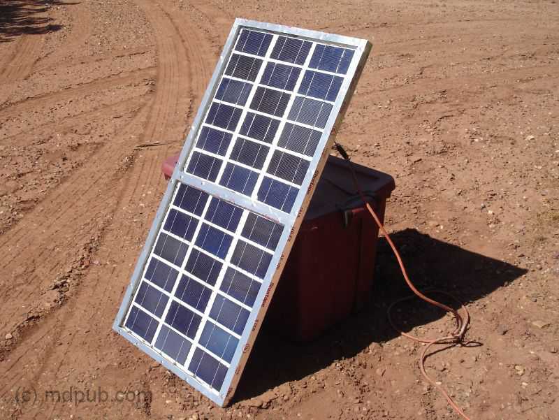
Here is a close-up of the solar panel. A write-up on how I built it can be found here. I have to move it several times each day to keep it pointed at the sun, but that isn’t really a big hardship. Maybe someday I will build a tracking system to automatically keep it aimed at the sun.
I have finally completed my second home-built solar panel. This is a smaller 15 Watt panel. It folds up for easier storage and transportation. Click the photo to learn more about it.
Here is a photo of the new charge controller unit. The wires on the left side are coming from the wind turbine and solar panel. The wires on the right side are going to the battery bank and dummy load. I cut up an old heavy-duty 100 ft. extension cord to make cables to connect wind turbine and solar panel to the charge controller. The cable to the wind turbine is about 75 feet long and the cable to the solar panel is about 25 feet long. The battery bank I am currently using consists of 11 sealed lead-acid 12V batteries of 8 Amp-Hour capacity connected in parallel. That gives me 88 Amp-Hours of storage capacity, which is plenty for camping. As long as it is sunny and windy, (nearly every day is sunny and windy on my property), the wind turbine and solar panel keep the batteries well charged.
Disaster! I went into town to pick up some supplies. While I was gone, a wind storm came up. Winds well in excess of 50 MPH blew through my area. When I returned I found the turbine in this condition. Two blades had snapped off, and the third was cracked, but still attached. The blades broke where the mounting tab met the body of the blade. I knew this was a weak spot and always expected they would break there eventually. I don’t know for sure if it was over-speed, or just fatigue from repeated flexing that caused them to break. I suspect fatigue though. I could see the blades flexing in strong winds before they broke. Interestingly though, I found that the battery bank was fully charged. The wind turbine must have generated some serious power in those high winds before it failed.
I knew I could get the wind turbine up and running again if I could just drill new mounting holes in the blades. I had no drill or drill bits with me though. I had to think about it for a while before I figured out how to do it. Then, the spirit of MacGyver came over me, and I knew just how to do it.
I figured out that if I heated my largest Phillips screwdriver over a fire, it would melt a hole in the PVC blades just the right size for the mounting bolts. So I got some charcoal going and started making holes. It’s a terrible abuse of a perfectly good screwdriver, but it was an emergency situation after all.
I used one of the broken mounting tabs as a template to locate where to make the holes in the bases of the blades. Then it was straightforward to just melt through the blades with the screwdriver. It was very quick and easy, and the holes were very clean.
I then re-mounted the blades on the hub of the turbine. I used the broken mounting tabs as spacers under the blades to prevent them from fouling the heads of the bolts that hold the hub together. The tabless blades are much stronger and less likely to flex in strong winds. I should have done it this way in the beginning. Live and learn.
Here is the turbine all re-assembled and ready to go back up on the tower.
Here is the wind turbine up and flying again. The loss of two inches of blade length doesn’t seem to have adversely impacted the performance of the turbine. It still works great. Not bad for an improvised repair job.
UPDATE 03/20/11
I have re-designed the battery charge controller circuit. It is now much less complex, and uses only easy to find parts, so it is much easier to build. Click the photo for more information.
UPDATE 06/06/11
I have made some modifications to the wind turbine. I have installed new blades that I bought on the internet. These blades are sold as replacements for the Air-X series commercially made wind turbines. They are more efficient than my home-made blades, and start up in lower wind speeds. I have also increased the tail area of the turbine since these new blades are both heavier and have more surface area than than my home-made blades. Check out the video for more information on the modifications.
The new and improved wind turbine really works great. It is now producing much more power, and working in lighter winds than before.
Water Collection and Storage: The best way to gather water is in a downspout barrel that collects rainwater. Obtaining water this way is safer than collection from a pond or stream since they have a much greater chance of contamination. It is also a good point to note that many survivalist are changing to metal roofing as its weatherproof,fireproof, and has a smooth surface that is less likely to contaminate your water supply.
WATER PURIFICATION
1) Clear water is a sign of pure water. Always drain long-standing pipes for 30 seconds to one minute before drinking!
2) 1 Gallon water is disinfected by 8-16 drops of regular household bleach (visually about 1/4 of a teaspoon) – double that for cloudy water. Shake and let stand 30 minutes. One teaspoon will disinfect 5 gallons. Immediately after treating, water must initially have a slight smell of chlorine. If it does not – repeat the process.
3) Household bleach is relatively harmless. The smell or �waft� of chlorine is not bad: it indicates that water is treated and germ free. Once treated and disinfected, the chlorine smell will go away in a few days.
4) Regularly used water from large tanks may be treated once or twice a month with 1 Oz. bleach per 200 gallons or 5 Oz. bleach per 1000 gallons.
5) Long-standing water in tanks will be disinfected w/ 1 pint household bleach per 1000 gallons. (2500 gal tanks are fine with 3 pints.)
6) Bleach effectively kills bacteria and viruses, stops smells and then breaks down. It’s effective germ killing alkaline property is completely neutralized very quickly. It does not stay chemically active in tanks for more than a few days. Most germs require sunlight to grow. Store water in the dark.
7) If water is relatively clear: but has a noticeable smell of chlorine: it is drinkable, disinfected, and harmless. Humans need 2 quarts per day.
Food Storage:
Food being a very important commodity in any disaster should be carefully maintained and in good supply. Having dozens of cans of spoiled food will not do you much good in a disaster so try to be diligent in disposing of out of date food. Salt is very important to keep a healthy supply of it has literally dozens of purposes first and foremost food preservation. I would recommend keeping several cases of both iodised and non-iodised salt on hand. Use the iodised for food preparation and the rest for attracting game, preserving meats, and even use it to relieve the swelling and pain of a bee sting. So get several times more salt than you think you’ll need.
Now that we have plenty of salt lets discuss dry foods such as, beans, rice, and pasta. Rice should be high up on your list as it has a pretty good shelf life of up to 10 years. I would suggest getting around 100 pounds for a family of 4, since this should last around a year if combined with other food stuffs.
I know this sounds like a lot but it is better safe than sorry. I would also recommend keeping a similar supply of oats and pasta as they store for long periods of time and take up relatively small amounts of space for the amount of food they produce. You can make flour from whole wheat that will last years longer than regular flour. You just need to buy whole grain wheat and grind it into flour yourself.
I recommend keeping a supply of olive oil (frozen, in plastic bottles it will last about 4 years), mayonnaise, canned butter, and peanut butter. These products should be date checked at least once a year and disposed of when spoiled. I would suggest donating items a few months before going out of date to ensure they get used. Hey, it will make you feel better to know you didn’t waste the money and help feed someone in need. When considering what type of milk to buy I would suggest purchasing nonfat nitrogen packed as it has the longest shelf life of up to 5 years. It is recommended to keep to have at least a case of each canned fruit, vegetables, and meat per person per year. More if you do not live close to where you can hunt and fish to replenish supply. Sugar is another important commodity that should be stored in similar quantity as salt. It is useful for many reasons besides sweetening your tea.
Some other useful items are plastic bags and containers. For trash bags I would suggest “Husky” brand yard bags for their durability and price. Another item of importance is aluminum foil as it will serve various purposes both in food storage and prep. Lastly, don’t forget spices,vinegar,baking soda, and yeast.
Pots and Pans: These items may seem at first self-explanatory, but they will serve many purposes during your ordeal. I would suggest you use cast iron if possible for cooking as they are nearly indestructible. I would get several sizes including a dutch oven. It is great for cooking on a stove or outdoors in a fire pit. Dont forget to have a really large stewpot as you will need it to boil water for drinking, bathing, laundry, and dishwashing. Dont forget to have butchering and skinning tools that you might need if your planning on hunting game.
Personal check list: Have each family member make a person checklist of items that they will need such as, spare glasses, medications, and necessary hygiene products. Lastly, don’t forget “Comfort” items to help get through high stress times. (Books, games, CDs, chocolates, etc.)
Needed First Aid and Surgical Equipment: It is very possible that you and your family will be cut off from medical facilities and professionals. So it will be important for you to have a well stocked first aid kit. Note, I do not mean one of those little crappy ones from Wal-Mart with 100 band aids and a few packs of generic antibiotic ointment. In your kit you should have at the minimum 100 band aids of various sizes per person as well as several rolls of gauze. Know that there will be a need at some point to treat burns make sure you have plenty of burn ointment on hand. It is also a good idea to put together a minor surgical kit for dental procedures and other life threatening injuries. Remember to include as many strong painkillers and tubes of dental ointment as you can. Dont forget to include a few spools of heavy-duty thread and several small gauge sewing needles. Buy a full minor surgery outfit you can find them online through several distributors. It may come in handy and its better to be prepared for the worst than find out you need it later. Lastly, I would recommend you include some crazy glue. its great for closing small cuts after they have been disinfected. They have similar products available at the local drugstore made for this purpose with disinfectant already inside.
Hygiene and Sanitary Supplies: Since it is doubtful you will have running water you will need to make some sort of outhouse( I know yuck) but it will be necessary. Powdered lime is a great choice for managing the smell and keeping down bacteria. Remember to have it well away from any water sources you might be using. We don’t want that getting into your drinking water. You will also want to have a good supply of soaps( hand, dish, and laundry), disinfectants, shampoo, toothpaste,sunscreen, and feminine products.
Lighting and Power: It will be a good idea to have several crank rechargeable lights on hand. I have many myself that also have a solar charging feature so try to look for those they come in handy. You will want to be careful when using lights at night since it will call attention to you. Make sure you have black out screens or curtains to give the impression f vacancy. People without provisions and equipment will be looking for those that do in order to acquire them. For power I would suggest having a solar unit but as so few of us (me included) have this a second choice would be a diesel fueled generator. Even if you do not use a diesel generator I would suggest getting the largest diesel tank you can afford to use for farming equipment, chain saws, and vehicles. It will be easier to find after a disaster. Dont forget to have at least a few large fire extinguishers readily available in case of a mishap.
Survival Clothing and Gear: Try to purchase earth tones clothing that will allow you to disappear into the brush should you come into contact with less than savory individuals. Include cold/foul weather gear for each member of your household. Synthetic double-bag (modular) sleeping bags for each person just in case you need to leave your home for the outdoors. Most importantly, get to know your neighbors this can not be stressed enough. They will either be you chief source of competition or your lifesaver in a disaster. Mark the names of each person you know well on a map so that you can reference it later in bartering situations.
Security: It will be important to have at least a few guns safely stored away will a good stock of ammunition. I know a lot of you abhor the use of guns, but in many disaster situations they will come in handy. They are good for hunting as well so make sure you buy extra ammo accordingly. It couldn’t hurt to stop by your local hunting supply and ask what the most popular brands of shot are. These will be worth a great deal in a disaster and can be used for bartering.
Necessary Tools: There are many tools you want to have on hand that you might not have thought of. Most of you will have assumed you would need tools for working on vehicles and equipment. It will also be good to have tools for gardening, construction, and wood working. Now that you have the tools you need make a list of items that you use regularly such as work gloves, nails, duct tape, twine, and glue.
Well now that you can’t fit into your attic or park your car in the garage your ready for a disaster or a nap. It isn’t necessary to look at any single survival list as complete. I would suggest looking at a few and making your own to fit your own needs.
The people liked the prospect of the end of the world because it would be a spectacle, something to relieve the fearful monotony of their lives. Funerals and weddings were commonplace, and nothing could have been so interesting to them as the coming of the end of the world … unless it had been a first-class circus. EDWARD EGGLESTON, The End of the World
10 Things That You Will Need when an Emergency Strikes
Many people do not know what they need in order to survive after a natural disaster. Most assume that they will just go down to the store and be given what they need. Other assume their church will get them through. Sadly, as seen with Katrina that will not be the case. It will be up to you to provide what you need that is why it is so important that you are prepared. Remember, nobody is going to prepare for you.
The following is a list of items that you will want to make sure that you and your family have in case you are faced with an emergency.
#1) Storable Food
Canned food is a priority when a disaster strikes as you will not be able to just run to your nearest grocery store to get what you want. In many cases you will be confined to your home for extended periods of time. You are going to need food that doesn’t require refrigeration as electricity will be scarce or non-existent. Even if you plan to growing your own food it is best to have a substantial amount of storable food put away.
#2) Clean Water
Most people could make it for a number of weeks without food, but without water you will die in a matter of days. You and your family are going to need clean water. Is there an abundant supply of water near your home? Will you be able to boil water if you need to? Without clean water you just are not going to survive for long.
#3) Shelter
In many natural disasters the possibility of losing your home is likely. What would you do if you lost your home or you were forced from your home? You and your family will need a safe warm place to sleep. Since, it is likely electricity will be unavailable make sure you have plenty of firewood on hand to keep you warm. In addition, always make sure you have a backup plan if you have to leave where you are at. Do you have family you can move in with if necessary? Do you have a tent that you could set up in the woods? If not take a look at the shelters v.s bunkers category for instructions on building an emergency shelter. Make sure you have a utility knife and tools needed to build your shelter.
#4) Warm Clothing
This is especially important if you live in a colder climate. You are your family need to prepare as if you would not be able to depend on the power company. Keep a store of clothing as if you would have to make it without heat if necessary. Always make sure to have plenty of blankets as well. Already there have been recent news stories this winter of people freezing to death inside their own homes after having their heat turned off. Don’t let that be you.
#5) Communication
This is especially important if you live in an isolated area. Always have a way to communicate with the outside world. Whether it is an emergency cell phone or something else, if you are able to call an ambulance in a timely manner it might save your life. Walkie-talkies are another way to communicate should phone service be unavailable. You can set up a local disaster network among you neighbors in order to give and receive assistance. It is those who are willing to work together that will have the best chance of making it.
#6) Lighters Or Matches
There may come a day when you need to start a fire in order to cook food or to boil water or to stay warm. When that day comes, do you really want to try rubbing sticks together to start a fire? Of course not. Now is the time to put away a supply of lighters or matches so that you will be prepared when you really need them. I would also recommend keeping a supply of steel wool and 9 volt batteries as you can immediately start a fire by putting the battery to the steel wool.
#7) Comfortable Shoes
This is an item that not a lot of people think of when it comes to survival. But what if you find yourself in an emergency situation where you are not able to use your car? What if you find yourself out in the wilderness far from the nearest town? Especially if you are headed out to a wilderness area, make certain to have some shoes on hand that will be comfortable.
#8) Flashlight And Plenty Of Extra Batteries
Just think about what happens when the power goes out now. What quickly becomes one of the most important items? A flashlight. Without a flashlight, you won’t be able to do much of anything after the sun goes down. Also, make sure you have plenty of extra batteries, because in a prolonged crisis your flashlight will be of little help without batteries.
#9) A Battery-Powered Radio
In a crisis situation, you will want to know what is going on in the world around you. A battery-powered radio can be a great source of information. You can even get a wind-up radio in some stores that doesn’t require batteries at all. Now, you can certainly survive without a radio, but you are your family will feel much better if you have some way of keeping track of what is going on out there.
#10) Sanitation Supplies And A First Aid Kit
Keeping a good emergency kit on hand will be very important to your survival. Untreated wounds will weaken if not outright kill you in an emergency situation where medical assistance might be scarce. In addition, what would you do without toilet paper or soap? I am sure you get the idea. Things can get unsanitary fast sp make sure that you and your family have plenty of supplies on hand.
(This can also be made with venison or other game meats)
This is a very good hearty stew that can be tailored to taste.
500 grams lamb (1 pound cubed)
75 grams butter (3 tablespoons)
6 thick slices of bacon
½dl vinegar (1/4 cup)
3 pickles
2 cloves
1 bay leaf
pinch tarragon
1 kilogram potatoes (2 pounds 2 ounces)
1 kilogram white cabbage (2 pounds 2 ounces)
4 onions
salt and pepper to taste
Season the lamb with salt and pepper. Quickly sear it on all sides in hot butter. Take the meat from the skillet and quickly fry the bacon. Cube the lamb, put it back into the skillet with the bacon, add 1½ dl water, the vinegar, chopped pickles and spices. Mix and let the stew simmer for 90 minutes.
In the meantime peel the potatoes, cut them into chunks and add to the stew. Clean and slice the cabbage, peel and dice the onions and add to the stew as well. Simmer for another 30 minutes. Add salt and pepper to taste.
100 grams/3.5oz. grated extra aged (Gouda) cheese (I usually substitute Cheddar and Colby in this recipe)
I like mine a little more seasoned so I usually add
1 teaspoon of red pepper
1 teaspoon of celery salt
1/2 cup of parmesan cheese
Boil the potatoes and when done drain the water and steam them for a minute or so. Let them cool. Purée the potatoes over a bowl.
Dice the bacon or pork slab. Put the butter in a hot skillet and when the foam starts to evaporate, put in the bacon bits. Turn down the heat and saute the meat till it is golden brown. Drain the grease into a small bowl to use later and put the bacon bits to the side.
Pour the grease into a large, heavy skillet. Add the onions and saute for two minutes. Put in the garlic and saute for a minute longer. Sift in the flour and mix well. While stirring add 2 quarts of water and stir until the mix boils. Add the stock cubes and milk and bring to a boil again.
Whisk in the mashed potatoes and turn down the heat. Add the sprig of rosemary and let the soup simmer for five minutes. Take out the rosemary and whisk the soup some more.
When the soup is ready to serve, fold in the bacon bits, cream and 4 tablespoons of chives. Pour in a heated serving dish or tureen. Sprinkle the rest of the chives over it. Allow your guests to add the grated cheese to the soup to taste.
I have been interested in building a solar energy system, but after looking at the prices I was seriously discouraged. I decided to see about making my own. This is a great, useful, and cost efficient way of producing solar panels. I hope to build a few of these very soon. I will say finding the ‘tabbed” 3/6 cells can be tricky. I hope you like this post as much as I did.
How I built an electricity producing Solar Panel It was easy. You can do it too
Share785
Several years ago I bought some remote property in Arizona. I am an astronomer and wanted a place to practice my hobby far away from the sky-wrecking light pollution found near cities of any real size. I found a great piece of property. The problem is, it’s so remote that there is no electric service available. That’s not really a problem. No electricity equals no light pollution. However, it would be nice to have at least a little electricity, since so much of life in the 21st century is dependent on it.
I built a wind turbine to provide some power on the remote property. It works great, when the wind blows. However, I wanted more power, and more dependable power. The wind seems to blow all the time on my property, except when I really need it too. I’ve also been experimenting with a biomass gasifier. With well over 300 sunny days a year on the property though, solar power seems like an obvious choice to supplement the wind turbine and gasifier.Solar panels are very expensive though. So I decided to try my hand at building my own. I used common tools and inexpensive and easy to acquire materials to produce a solar panel that rivals commercial panels in power production, but completely blows them away in price. Read on for step by step instructions on how I did it.
Here is a video of the solar panel set up and in use on my remote, off-grid property.
Let me state up front that I probably won’t be able to help you out much if you decide to build your own solar panel(s). This web site has become insanely popular, often taxing the bandwidth limits of the server. I get dozens of requests for help each day. I simply don’t have time to answer the majority of them. Most of the questions and requests I get are the same ones over and over again. I have created a FAQ to handle these repetitive questions. Please read it before emailing me. Simple questions, not covered by the FAQ,which only require a quick and simple answer may get replies if time permits. However, there is no way I can help you out with complex issues, teach you electronics theory, help you locate parts, build a charge controller for you, or custom design a system for you. There just aren’t enough hours in the day. Sorry.
So what is a solar panel anyway? It is basically a box that holds an array of solar cells. Solar cells are the things that do the actual work of turning sunlight into electricity. However, it takes a lot of cells to make a meaningful amount of power, and they are very fragile, so the individual cells are assembled into panels. The panels hold enough cells to make a useful amount of power and protect the cells from the elements. It doesn’t sound too complicated. I was convinced I could do it myself.
I started out the way I start every project, by Googling for information on home-built solar panels. I was shocked at how few I found. The fact that very few people were building their own panels led me to think it must be harder to do than I thought. The project got shelved for a while, but I never stopped thinking about it.
After a while, I came to some conclusions:
The main stumbling block to building solar panels is acquiring solar cells at a reasonable price.
New solar cells are very expensive, and can even sometimes be hard to find in quantity at any price.
Blemished and damaged solar cells are available on Ebay and other places at a fraction of the cost of new perfect cells.
These second rate solar cells could probably be used to make a solar panel that would work just fine.
Once I came to the realization that I could use blemished and factory-second solar cells to build my panels, I finally got to work. I started by buying some solar cells off of Ebay
I bought a couple of bricks of 3 X 6 mono-crystalline solar cells. It takes a total of 36 of these type solar cells wired in series to make a panel. Each cell produces about 1/2 Volt. 36 in series would give about 18 volts which would be good for charging 12 volt batteries. (Yes, you really need that high a Voltage to effectively charge 12 Volt batteries) This type of solar cell is as thin as paper and as brittle and fragile as glass. They are very easily damaged. The seller of these solar cells dips stacks of 18 in wax to stabilize them and make it easier to ship them without damaging them. The wax is quite a pain to remove though. If you can, find cells for sale that aren’t dipped in wax. Keep in mind though that they may suffer some more damage in shipping. Notice that these cells have metal tabs on them. You want cells with tabs on them. You are already going to have to do a lot of soldering to build a panel from tabbed solar cells. If you buy cells without tabs, it will at least double the amount of soldering you have to do. So pay extra for tabbed cells.
I also bought a couple of lots of cells that weren’t dipped in wax from another Ebay seller. These cells came packed in a plastic box. They rattled around in the box and got a little chipped up on the edges and corners. Minor chips don’t really matter too much. They won’t reduce the cell’s output enough to worry about. These are all blemished and factory seconds anyway. The main reason solar cells get rejected is for chips. So what’s another chip or two? All together I bought enough cells to make 2 panels. I knew I’d probably break or otherwise ruin at least a few during construction, so I bought extras.
There are lots of other sizes of solar cells besides 3 X 6 inches available. You could use larger or smaller cells for your panel. Just keep a few things in mind.
Cells of the same type all produce the same voltage no matter what size they are. So the same number of cells is always needed.
Larger cells produce more current (Amps) and smaller cells produce less current.
The total power your panel can produce is determined by Amps X Volts.
So using bigger cells produces more power, but the panel will be large and heavy. Using smaller cells keeps the panel small and light, but won’t produce as much power. Also, mixing cell sizes is not a good idea. This is because the current your panel can produce will be limited by the smallest cell in the group and the larger cells won’t work to their full potential.
The cells I settled on are 3 X 6 inches in size and are rated at roughly 3 amps. I will wire 36 of them in series to get a little over 18 volts. The result should be a panel capable of delivering almost 60 Watts of power in bright sunlight. It doesn’t sound like a lot, but it sure beats no power at all, which is what I had on my property before. And that is 60 Watts all day when the sun is shining. That power will go into charging batteries which will primarily be used for powering lights and small appliances for only a few hours after dark. Once I go to bed, my power requirements drop to almost nothing. So 60 Watts is actually quite a lot of useful power, especially when I also have my wind turbine adding to the power production when the wind is blowing.
After you buy your solar cells, put them away in a safe place where they won’t get dropped, played with by the kids, or eaten by the dog until you are ready to install them in the panel. These cells are very fragile. Rough treatment and excessive handling will turn your expensive solar cells into little, blue, shiny shards that aren’t useful for anything.
A solar panel is really just a shallow box. So I started out by building myself a shallow box. I made the box shallow so the sides wouldn’t shade the solar cells when the sun comes at an angle from the sides. It is made of 3/8 inch thick plywood with 3/4 X 3/4 pieces of wood around the edges. The pieces are glued and screwed in place. This panel will hold 36 3 X 6 inch solar cells. I decided to make 2 sub-panels of 18 cells each just so make it easier to assemble later. So there is a center divider across the middle of the box. Each sub-panel will fit into one well in the main panel.
Here is my sort of back of the envelope sketch showing the overall dimensions of the solar panel. All dimensions are in inches (sorry you fans of the metric system). The side pieces are 3/4 by 3/4 and go all the way around the edges of the plywood substrate. also a piece goes across the center to divide the panel into two sub-panels. This is just the way I chose to do it. There is nothing critical about these dimensions, or even the overall design. Feel free to deviate in your own design. These dimensions are included here for those people who always clamor for me to include dimensions on my projects. I always encourage people to experiment and innovate on their own, rather than blindly follow the way I (or anyone else) does things. You may well come up with a better design.
Here is a close-up showing one half of the main panel. This well will hold one 18 cell sub-panel. Notice the little holes drilled in the edges of the well. This will be the bottom of the panel (it is upside down in the photo, sorry). These are vent holes to keep the air pressure inside the panel equalized with the outside, and to let moisture escape. These holes must be on the bottom of the panel or rain and dew will run inside. There must also be vent holes in the center divider between the two sub panels.
Update: After using the panel for a while, I now recommend that the vent holes be increased to at least 1/4 inch in diameter. Also, to keep dust and critters out of the panel, stuff a little fiberglass insulation in the holes in the bottom rail of the panel. The insulation is not needed in the holes in the center divider.
Next I cut two pieces of masonite peg-board to fit inside the wells. These pieces of peg-board will be the substrates that each sub-panel will be built on. They were cut to be a loose fit in the wells. You don’t have to use peg-board for this. I just happened to have some on hand. Just about any thin, rigid and non-conducting material should work.
To protect the solar cells from the weather, the panel will have a plexiglass front. Here two pieces of scrap plexiglass have been cut to fit the front of the panel. I didn’t have one piece big enough to do the whole thing. Glass could also be used for this, but glass is fragile. Hail stones and flying debris that would shatter glass will just bounce off the plexi. Now you can start to see what the finished panel will look like.
Oops! This photo shows a close-up of where the two halves of the plexiglass cover meet over the center divider. I drilled and countersunk holes all around the edges of both pieces of plexiglass so I could screw them onto the face of the panel with 1 inch drywall screws. Be careful working close to the edge of the plexi. If you get to aggressive it will break, as happened here. I just glued the broken piece back in and drilled another hole a short distance away.
Next I gave all the wooden parts of the panel several coats of paint to protect them from moisture and the weather. The box was painted inside and out. The type of paint and color was scientifically chosen by shaking all the paint cans I had laying around in my garage and choosing the one that felt like it had enough left in it to do the whole job.
The peg-board pieces were also painted. They got several coats on both sides. Be sure to paint them on both sides or they will curl when exposed to moisture. Curling could damage the solar cells that will be glued to them.
Now that I had the structure of the panel finished, it was time to get the solar cells ready
As I said above, getting the wax off the cells is a real pain. After some trial and error, I came up with a way that works fairly well. Still, I would recommend buying from someone who doesn’t dip their cells in wax. The first step is a bath in hot water to melt the wax and separate the cells from each other. Don’t let the water boil or the bubbles will jostle the cells against each other violently. Also, boiling water may be hot enough to loosen the electrical connections on the cells. I also recommend putting the brick of cells in the water cold, and then slowly heating it up to just below boiling temperature to avoid harsh thermal shocks to the cells. Plastic tongs and spatulas come in handy for teasing the cells apart once the wax melts. Try not to pull too hard on the metal tabs or they may rip off. I found that out the hard way while trying to separate the cells. Good thing I bought extras.
This photo shows the complete setup I used. My girlfriend asked what I was cooking. Imagine her surprise when I said solar cells. The initial hot water bath for melting the wax is in the right-rear. On the left-front is a bath of hot soapy water. On the right-front is a bath of hot clean water. All the pots are at just below boiling temperature. The sequence I used was to melt the bricks apart in the hot water bath on the right-rear. I’d tease the cells apart and transfer them one at a time to the soapy water bath on the left-front to remove any wax on the cell. Then the cell would be given a rinse in the hot clean water on the right-front. The cells would then be set out to dry on a towel. You should change the water frequently in the soapy and rinse water baths. Don’t pour the water down the sink though, because the wax will solidify in your drains and clog them up. Dump the water outside. This process removed almost all the wax from the cells. There is still a very light film on some of the cells, but it doesn’t seem to interfere with soldering or the working of the cells. A solvent bath would probably remove the rest of the wax, but that would be dangerous and stinky since the only solvents I could think of that would cut wax are either flamable, toxic or smelly, or all three.
Here are some separated and cleaned solar cells drying on a towel. Once separated from their wax stabilized brick form, they are amazingly fragile and difficult to handle and store. I would recommend leaving them as bricks until you are ready to install them in your panel. That way you won’t wreck them before you get to use them. So build the panel first. Now it’s time to start installing them in the panel
I started out by drawing a grid pattern on each of the two pieces of pegboard, lightly in pencil, so I would know where each of the 18 cells on them would be located. Then I laid out the cells on that grid pattern upside-down so I could solder them together. All 18 cells on each half panel need to be soldered together in series, then both half panels need to be connected in series to get the desired voltage.
Soldering the cells together was tricky at first, but I got the hang of it fairly quickly. Start out with just two cells upside-down. Lay the solder tabs of one cell across the solder points on the back of the other cell. I made sure the spacing between the cells matched the grid pattern.
I used a low-Wattage soldering iron and fine rosen-core solder. I also used a rosen pen on the solder points on the back of the cells before soldering. Use a real light touch with the soldering iron. The cells are thin and delicate. If you push too hard, you will break the cells. I got careless a couple of times and scrapped a couple of cells.
UPDATE 04/01/10
A lot of people write me confused about how to solder the solar cells together. When a hundred people all ask the same question, it’s obvious I am not being clear in this area. A lot of people look at the photos and assume I am soldering the cells in parallel instead of in series. I have created this crude sketch to hopefully clear things up. This is a side view of the solar cells soldered together. The negative tabs from the top of one cell are soldered to the positive pads on the bottom of the next. This connects the cells in series, and adds their voltages. I do this until I have a string of 6 cells. 3 strings of 6 make a half panel. I hope that helps.
I repeated the above steps and soldered solar cells together until I had a string of six cells. I soldered tabs from scrapped cells to the solder points on the back of the last cell in the string of six. Then I repeated the whole process two more times to get three strings of six cells for a total of 18 for this half of the panel.
The three strings of cells need to be wired in series. So the middle string needs to be rotated 180 degrees with respect to the other two. I got the strings oriented the way I wanted them (still upside-down) on top of the pegboard panel before the next step of gluing the cells in place.
Gluing the cells in place proved to be a little tricky. I placed a small blob of clear silicone caulk in the center of each cell in a six cell string. Then I flipped the string over and set in place on the pencil line grid I had laid out earlier. I pressed lightly in the center of each cell to get it to stick to the pegboard panel. Flipping the floppy string of cells is tricky. Another set of hands may be useful in during this step.
Don’t use too much glue, and don’t glue the cells anywhere but at their centers. The cells and the panel they are mounted on will expand, contract, flex and warp with changes in temperature and humidity. If you glue the cells too tightly to the substrate, they will crack in time. gluing them at only one point in the center allows the cells to float freely on top of the substrate. Both can expand and flex more or less independently, and the delicate solar cells won’t crack.
Next time I will do it differently. I will solder tabs onto the backs of all the solar cells. Then I will glue all the cells down in their proper places. Then I will solder the tabs together. It seems like the obvious way to go to me now, but I had to do it the hard way once to figure it out.
Here is one half panel, finally finished.
Here I used copper braid to interconnect first and second strings of cells. You could use solar cell tabbing material or even regular wire. I just happened to have the braid on hand. There is another similar interconnection between the second and third strings at the opposite end of the board. I used blobs of silicone caulk to anchor the braid and prevent it from flopping around.
Here I am testing first half panel outside in the sun. In weak sun through clouds the half panel is producing 9.31 Volts. YAHOO! It works! Now all I had to do is build another one just like it.
Once I had two half panels complete, I could install them in their places in the main panel frame and wire them together.
Each of the half panels dropped right into their places in the main panel frame. I used four small screws (like the silver one in the photo) to anchor each of the half panels in place.
Wires to connect the two half panels together were run through the vent holes in the central divider. Again, blobs of silicone caulk were used to anchor the wire in place and prevent it from flopping around.
Each solar panel in a solar power system needs a blocking diode in series with it to prevent the panel from discharging your batteries at night or during cloudy weather. I used a Schottky diode with a 3.3 Amp current rating. Schottky diodes have a much lower forward voltage drop than ordinary rectifier diodes, so less power is wasted. Every Watt counts. I got a package of 25 31DQ03 Schottky diodes on Ebay for only a few bucks. So I have enough left-overs for lots more solar panels
My original plan was to mount the diode inline with the positive wire outside the panel. After looking at the spec-sheet for the diode though, I decided to mount it inside since the forward voltage drop gets lower as the temperature rises. It will be warmer inside the panel and the diode will work more efficiently. More silicone caulk was used to anchor the diode and wires.
I drilled a hole in the back of the panel near the top for the wires to exit. I put a knot in the wires for strain relief, and anchored them in place with yet more of the silicone caulk.
It is important to let all the silicone caulk cure well before screwing the plexiglass covers in place. I have found through past experience that the fumes from the caulk may leave a film on the inside of the plexiglass and the cells if it isn’t allowed to thoroughly cure in the open air before screwing on the cover.
And still more silicone caulk was used to seal the outside of the panel where the wires exit.
I added a polarized two-pin jones plug to the end of the panel wires. A mating female plug will be wired into the charge controller I use with myhome-built wind turbine so the solar panel can supplement its power production and battery charging capacity.
UPDATE: 10/12/09
I’ve been getting a lot of emails from people giving me grief for using a male plug on the solar panel. They say that power sources should always have female pugs on them to prevent short circuits. I understand their point. However, the reason I used the male plug on the solar panel is because there is a much greater danger of a short circuit on the cable going to the charge controller and battery bank. The solar panel can only supply 3 Amps to a short circuit at most. The battery bank though could pump hundreds or possibly thousands of Amps through a short circuit. That is enough energy to do serious damage. So I put the female end on the cable to the charge controller. Still, I agree that it is dangerous to have a male plug on the solar panel. On a recent trip to Radio Shack I found this sort of plug. It only cost a few bucks and will solve the potential short circuit problem. When unplugged, neither end can short out.
Here is the completed panel with the plexiglass covers screwed into place. It isn’t sealed shut yet at this point. I wanted to wait until after testing it because was worried that I might have to get back inside it if there were problems. Sure enough, a tab popped off one of the cells. Maybe it was due to thermal stresses or shock from handling. Who knows? I opened up the panel and replaced that one cell. I haven’t had any more trouble since. I will probably seal the panel with either a bead of silicone caulk, or aluminum AC duct tape wrapped around the edges.
Here I am testing the Voltage output of the completed panel in bright winter sunlight. My meter says 18.88 Volts with no load. That’s exactly what I was aiming for.
Here I am testing the current capacity of the panel, again in bright winter sunlight. My meter says 3.05 Amps short circuit current. That is right about what the cells are rated for. So the panel is working very well.
So how much did all this cost to build? Well, I saved all the receipts for everything I bought related to this project. Also, my workshop is well stocked with all sorts of building supplies and hardware. I also have a lot of useful scrap pieces of wood, wire and all sorts of miscellaneous stuff (some would say junk) lying around the shop. So I had a lot of stuff on hand already. Your mileage may vary.
Not too bad. That’s a fraction of what a commercially made solar panel with a comparable power output would cost, and it was easy. I already have plans to build more panels to add to the capacity of my system. I’ll post more here as the project evolves. Stay tuned
Once again I stayed on my remote property during my recent vacation in Arizona. This time I had both my home-built wind turbine and my home-built solar panel with me. Working together, they provided plenty of power for my (admittedly minimal) electricity needs.
Here is a close-up of the solar panel in action. I have to move it several times each day to keep it pointed at the sun, but that isn’t really a big hardship. Maybe someday I will build a tracking system to automatically keep it aimed at the sun.
UPDATE 10/12/09
Here is a close-up of the solar panel after having the edges sealed with aluminum tape. This is not the cheap duct tape. This is the thin metal tape with an adhesive backing. I applied it all the way around the edges of the panel and across the center seam. I burnished it down well to make a good seal. I was careful to punch out the vent holes so they wouldn’t be blocked. The tape seems to be quite weather-proof, and the panel seems to be thoroughly sealed and protected. Only time will tell how well it works. However, since my panels are only outdoors when I am staying on my remote property, and are not exposed to the weather all the time, I suspect it will hold up well for a long time.
The Aluminum tape gives the panel a whole new look. It looks like the frame is made of metal, rather than wood. To my eye, it looks a lot more professional.
I have also completed a second solar panel. This is a smaller 15 Watt panel. It folds up for easier storage and transportation. Click the photo to learn more about it.
UPDATE 03/20/11
I have designed a simple battery charge controller circuit for use with solar panels and wind turbines. It is a simple circuit, and it uses only easy to find parts, so it is very easy to build. Click the photo for more information.
UPDATE 11/02/11
This is a photo of my new home-built solar tracking platform for one of my home-made 60 Watt solar panels. Actually, I could get two panels on this tracker, but I only have one mounted now for testing. This is really just a teaser photo because the tracker isn’t finished yet. I am still working on the electronics to drive it. The structure was mostly completed a couple of days ago, and I got this nice photo of it set up in my workshop. It probably won’t be completely done for another month or two. Then I will put up a full write-up on how I built it. I will tell you this much about it now. It is driven by a 1960s vintage antenna rotator. The structure is designed to come apart for eventual transport to my remote Arizona Property. It was also cheap and easy to build. Stay tuned for future updates on this project.
Obtained from: “The Practical Handymans Encyclopedia’
Note: Before beginning this or any permanent structural project please consult a building professional to ensure your safety.
Some good suggestions that’ll make your job an easier one
If you should want to build your own shelter, how would you go about it? First of all, you need a sharp pencil and a lot of paper. Shelter plans are designed for the average person. You are not the average person. You have special needs,and your shelter will he better suited for you if you design it for those needs.OCDM plans are excellent, but let them be a guide only .You must decide what type of shelter fits your individual needs. Each type of shelter has its own type of plans and problems.
Finally, you should make a tour of all suppliers for bids. You will find prices vary from place to place.If you live in or near a large city, check with local wrecking companies. These places offer excellent buys in good used materials at prices far below new products. Check all material for nails and termite damage. Also with all suppliers, have them include delivery,prices with the materials. Many of these items are much too heavy or bulky to be carried by car. Some suppliers deliver free.
Others make a charge for every delivery. lf the latter is the case, plan your purchases to lower the number of deliveries.
No matter what type of shelter you build, working with concrete will be a major part of the construction. Concrete blocks are probably the easiest material to use in shelter construction because of their ease of handling and good protection factor. Poured concrete slabs can also be used, with heavy half-inch steel rod embedded, for strong roof and wall sections of a shelter, but for the average do-it-yourselfer, it is much easier to build these sections of block and to brace them from within the structure. It is also much cheaper. Standard size for a cinder block is 8x8x12 inches. Solid concrete blocks in standard size is 4x8x16 inches, although many other sizes are available, or you can cut these to a size that is needed. In figuring number of blocks needed, don’t forget to allow for space mortar will fill in a series of blocks. A good rule of thumb for walls is that a wall eight blocks high will give you a ceiling just over six feet above your head.
A footer row of blocks will be your first problem in building with blocks. If this first row of blocks is to be laid on a cement floor, such as you would have in building a basement shelter, a key way or slot must be cut in the present basement floor with a chisel. This is cut the width of a cinder block and then dug out to accommodate all but the top of a cinder block. After the key way has been cleaned out, a layer of black polyethylene 6 mil insulation material should be laid to prevent moisture from seeping up through the floor. Cut this material so it will cover the bottom and both sides of the key way! and leave an inch or so above the floor level.
Mortar is then poured along this key way and the first set of blocks set into place. This will make a secure lock for your walls foundation. Many states require that the footing for a block wall be poured as one continuous operation. Additional locking for walls can be had by knocking a hole into the existing basement wall at the end of each row of blocks put up. The end block of each row is then mortised into the existing wall by about half its length.The footer for a row of blocks set into the ground is done much the same way, except it is advisable to place at least two blocks below ground level. This will make walls more secure than using a shallow footing. Mortar used in all concrete construction for a shelter should be a mixture designed for earthquake areas: 1 part masonry cement 1 part portland cement 4-6 parts mortar sand. To mix your mortar, work all the dry ingredients together thoroughly in the proportions above. Then slowly add a little water and mix some more. If too heavy, repeat. It is better to use too little water than even a little bit too much. When ready for use, the mortar should be a workable plastic mixture. If the mortar dries a little faster than you are using it, add a little more water as you need it, and remix. A good test for your mortar is to put a shovel full aside from the mix, and if it stands alone without spreading, and no water runs off, your mortar should be just right.
Don’t try to economize on mortar. One fellow used the dirt he was taking from the site of his shelter for the second part of his mix. It was much too coarse. and his project met with disaster. You can build a mortar box for mixing from a sheet of plywood. It is just as cheap and more convenient to mix in a wheelbarrow. When ready, the mortar can be wheeled to your working site A hoe will be the easiest too to use in making your mlx.Another tool you must have is a long mason’s level. Every block you lay must be checked to make sure it is level. Every row of blocks must also he tested to make sure they are level. A 2×4 can be used to tap several blocks down evenly and neatly.Once your footer, or base, for all your walls is in place, and level, you are then ready to start your wall up in rows.
Start laying your first row at a corner, not on the end of a footer row. Place the blocks in the opposite position of the blocks on the footer row. This will put the mortar seams above a solid part of the block below, not above another seam. Alternate the position of the blocks like this in every other row. If your row does not come out the exact length desired, don’t worry. Merely trim part of the last block in a row with a mason’s hammer. As the row of blocks goes up, use you’ll level along the vertical line of the wall to make sure the rows are straight. Excessive mortar should be scraped off blocks with a trowel as soon as possible.A neat job of making a professional-looking joint between two blocks can be done by making a “V” in the mortar with a stick. As the walls to your shelter go up you can get more radiation protection by filling the holes in cinder blocks with dirt. This may not be needed in a basement shelter, but in other types it is highly desirable.
Now is the time to use some of the dirt you excavate from your yard. When you have reached the top row of your shelter’s wall, either the basement or other types, you can now put in the supports for your
ceiling. The ceiling will have a great amount of weight, so more than a normal amount of supporting must be done. Steel beams are best, placed close together, as many as you can afford. Next best are
wooden beams of at least 2×6. Two 2×6 beams nailed together and set on the row of blocks will make a support 4 inches wide and six inches high. Spaced four inches apart, and braced together with lumber, these beams will make a strong support. All space around the ends of the beams on the block wall are then filled with mortar to the top of beams.You are now ready for the first layer of your roof. The easiest thing to use for this is two layers of 1 inch plywood sheets. It would be
better if these were nailed to the supports. but if you can’t reach the centers in a basement shelter you can nail them down along the edges. The weight of the next layer will hold them in place.
On top of the plywood, lay two rows of solid concrete blocks (4x8x16), to make a radiation shield 16 inches thick. These blocks are merely laid tightly into place.There is no need to mortar them together.Inside support for walls can be had by bolting 4×4’s up the entire height of the wall. Let the top ends of these vertical supports wedge under the roof supports. If this job is done before mortar has completely set it will be much easier to position bolts and they will be locked tighter into the wall by the still wet mortar. These vertical supports can also be used later to hang bunks and storage shelves, but make certain plenty of support under these additions is provided to keep strain off wall support, and thus defeating their purpose. Basement shelters have some special
design problems of their own. If doors and windows in the basement are blocked by sandbags, air filtering for this type of shelter will not be necessary. To provide a good air supplier, leave a row of small holes along the second row of wall blocks from the floor level. Also, a second false wall, to act as a radiation baffle, can be constructed as part of the shelter across the door. This can be left open to allow passage of air. When planning your basement shelter, try to make it a dual-purpose
room. If head room is sufficient, a TV room, playroom, den, or darkroom can be had by adding inside paneling to the walls. The size of a basement shelter is not too important. It will depend how much of your basement you are willing to turn over for this purpose, and upon how
many people must be sheltered. A 10 x10-foot shelter is designed to accommodate six people.
Earth covered shelters present a number of problems that are not met in the construction of a basement shelter. Let us look at each of these problems separately:
(A) Excavate or Tunnel? If your house has a basement this will be the first decision you must make. Should the shelter be attached to the house through the basement, or should it be completely away from the house. The preshaped shelter which is built at least partially above
ground because of a high water table or a rock condition to solve the problem for you. It would be most difficult to connect it with the house basement.
The underground shelter is a different
matter. Here you have a choice. Actually, it makes little difference. It might be more convenient to attach the shelter to the basement by means of a connecting tunnel, but your shelter will be just as effective with an outside entrance. An inside entrance from your basement, however, will probably be a little cheaper to build. The method you use to dig out the ground for your underground shelter may also cause you to ponder. You can either remove the dirt from above ground, by digging down, or you can tunnel below ground from your basement. You may want to tunnel if you don’t want to tear up the lawn, or if a number of large trees are over the spot you elect for a shelter. If you do tunnel, be extremely careful about cave ins. Shore up as you work and tunnel only small areas at a time. This method will be much slower and will cost some more than cutting down from the surface. If you do dig down from the surface you can do the work by hand, but it will require a lot of shoveling and time.If the extra money is unavailable, it would be much faster and less labor involved to hire a tractor scoop to come in and do the job within a few hours time. Any connection you may decide to make between your house and your shelter, such as air vents, water lines, or
electricity, should be put in place before dirt is replaced.
(B) Heat: A small wood burning stove in your shelter would be ideal to supply heat and for cooking. A hot water heater type available from Sears or Wards would be a good choice. But in either an underground or basement shelter, a stove of this type must be vented to keep fumes from filling the shelter. A vent pipe should be run out of the shelter before construction has been completed, if a stove is considered. The outside of the vent pipe should have a gooseneck hood to prevent
radioactive fallout from coming down vent pipe. Aluminium vents would be better for underground use because of rusting danger with other metals. To prevent a fire hazard make sure vent pipe does not touch any wood.
(C) Water: This item of survival is your most precious one. Men have lived for days without food, but only for hours without water. A simple, yet excellent supply of water can be had by driving a pipe down through the floor of the shelter until water is reached. Then fasten an old-fashioned hand pump to the pipe. But don’t forget to have several gallons of water on hand to prime this type of pump. You must pour water down from the top and pump it back up to start the operation of the pump. A pump of this type can be had from either Sears or other online retailers.
(D) Waterproofing and Drainage: This is the problem common with all earth covered shelters. You must keep water from seeping or running into the shelter after heavy rains or melting snows begin.
If you do a careful preventive job while your shelter is under construction, you should not have a problem.
There are three lines of attack against moisture. You should use all three:
1. Ditching:
Around each wall of your shelter, dig a trench one foot wide and one foot deep. Fill this trench with six inches of gravel and rock. Then, from each corner of the shelter, run clay drain pipes for at least S2X feet away from foundation. Make sure you slant them down and away from your
foundation. If you dig a hole at the end of each rain and fill this with rock, it will also help.
2. Paint:
Special waterproofing paint should then be applied to both the inside and outside surfaces of the
walls
3. Vapor Barrier: Black polyethylene 6 mil insulating plastic sheets can help stop water from entering through the floor and roof. As a final touch these cracks.
(E) Roof: With a combination of weight from earth and concrete blocks on it. An earth covered roof must be extra strong. It must also be waterproof. The same roof as was outlined for the basement shelter can be used here for maximum blast and radiation protection, but at least three feet of earth must also cover it. Supports for this roof must be at least equal to those described for the basement shelter. Added strength can be gained by running another concrete wall through the center of the shelter for added center support of the roof. Over the solid concrete blocks a large sheet of black polyethylene should be laid, with the edges overlapping the edge of the blocks by at least a foot. On top of this place sheets of corrugated aluminium of at least .019 inches in thickness. Steel would do as well, but would rust Before dirt is filled in on top of shelter,add another layer of polyethylene.
(F) Air: When the door of an underground shelter, or the door on a preshaped earth-covered shelter closes, radiation is closed out, but so is the vital air supply needed for human life. Some means must be provided to get safe ventilation to the people inside these types of shelters.
Plans issued by the OCDM for shelters of this type provide for the intake of fresh air through vertical pipes reaching upward through the roof of a shelter. Attached to the end of the vent, inside the shelter, is a hand-operated blower to suck the air into the shelter through filters. There is a question, however whether these projection air vents would not be snapped off in the high winds and pressures that would be encountered near a 20-megaton blast. It is not until you get 15 miles away from such a blast that the winds subside to 80 mph speed that is considered dangerous in a hurricane. Pressure from the blast at this range will be down to 2.3 psi. The situation is much better at 20 miles where winds are then down to 40 mph a mere breeze when compared with those
encountered from 15 mph on in toward the blast. Pressure at 20 miles has also dropped to about 1.3 psi. Official Atomic Energy Commission tests held in Nevada in 1950 showed that in the area where pressures reached 30 pounds per inch, a one-half-inch pipe was bent to the round and the valve handle, stem, and bonnet were blown off. At the same location two 4-inch ventilating pipes were sheared off just below ground level. Pressures up to 30 psi are encountered from a 20-megaton blast up to three miles away from ground zero. vertical vents on shelters as shown in CD plans, would have a good chance of being cut off or bent to the ground, leaving the occupant of the shelter with no air supply. If your shelter is to be located within 20 miles of a potential target, it seems prudent to this author that the owner of such a shelter install a type of ventilating system that would be protected from such hazards. A system of retractable vents would work nicely, but
the Atomic Energy Commission has advised that the cost for a safe system of this type would be much too high for the average shelter owner.
A relatively inexpensive method for providing air through a ventilating system safe from high winds and pressures is an underground type. By using a natural embankment, or making one at the edge of your yard, you have a vent come into your shelter under the ground. This vent is of the type used on hot-air furnaces, and it can be made of aluminium by any metal shop. Aluminium should be used to prevent rusting of the buried unit. A large diameter pipe could also be Used but there are two reasons for the rectangular type. A coal chute door of steel can be attached to the outside end of the vent. This can be shut from the inside during the most severe conditions; it can then be opened from the inside to allow air to enter the shelter. It will also accommodate a fiberglass filter used on furnaces. You can have the vent made as large as you like, but a 20×25-inch opening should be the limit. Of course, the larger the Vent the larger the air flow. The entire vent system is braced at least three feet underground by a frame of 2×4’s. Attached to the frame is a series of pulleys for opening the steel door from inside the shelter by a 4-inch steel rope. Another steel rope runs down inside the vent to close it. Another use for the vent might be for an emergency escape hatch, in the event the shelter door was damaged by blast, or was blocked by debris. The steel rope, normally used to close the steel vent door, would then be used to allow a person to pull himself up through the vent. The vent would enter the shelter near the floor level, and a similar vent, near the ceiling of the shelter, could be used to carry off stale air, smoke, or fumes. This second vent could easily be a round stovepipe made from aluminium, and available from suppliers ready-made. The exhaust vent should also have an air filter on it, too. The outside ends Or all vents should be shielded from above to keep fallout from coming down the vents line. Fallout particles are about the size of an average drain of
salt or sugar, reduced in size from one tenth to one half. They are in the shape of small spheres of teardrop shaped cinders or ashes. These particles settle to earth the same as dust and enter the same places dust can. To keep these specks of radioactive dust from entering the shelter with pure air, a filtering system is needed. Filters of glass fiber block or other fibrous material is very effective for this job. Inexpensive filters of fiberglass that are used for a home furnace are of this type. Filters are also commercially available which have been designed for shelter use. A blower, either hand-operated or electrically driven can be attached in the shelter to pull air in at a faster rate than will normally flow into the shelter.
(G) Doors: The door of your shelter must he considered one of the most important pieces of equipment for the shelter. In a quote from the Atomic Energy Commission points this out “This is the first line of defense against blast and radiation; failure to lock the door could be disastrous.The size and the type of door you pick for your shelter will depend upon several factors, but whatever your choice is, you must pick a steel door that can be locked from the inside by some type of bolt,
and it must be hung in a steel and cement frame.The door is all important!


 Several years ago I bought some remote property in Arizona. I am an
  I managed to score one of the good 30 volt Ametek motors off of
  I followed their general recipe. I did things a little differently though. I used black ABS pipe since my local homecenter store just happened to have pre-cut lengths of it. I used 6 inch pipe instead of 4 inch and 24 inches long instead of 19 5/8. I started by quartering a 24 inch long piece of pipe around its circumference and cutting it lengthwise into four pieces. Then I cut out one blade, and used it as a template for cutting out the others. That left me with 4 blades (3 plus one spare).
 I then did a little extra smoothing and shaping using my belt sander and palm sander on the cut edges to try to make them into better airfoils. I don’t know if it’s really much of an improvement, but it didn’t seem to hurt, and the blades look really good (if I do say so myself).
 Now I needed a hub to bolt the blades to and attach to the motor. Rummaging around in my workshop, I found a toothed pulley that fit on the motor shaft, but was a little too small in diameter to bolt the blades onto. I also found a scrap disk of Aluminum 5 inches in diameter and ¼ inch thick that I could bolt the blades onto, but wouldn’t attach to the motor shaft. The simple solution of course was to bolt these two pieces together to make the hub.
 Much drilling, tapping and bolting later, I had a hub.
 Here it is assembled and with the blades attached (after drilling mounting holes in them of course).
 Here is another view of the hub with blades attached.
 On a trip to the homecenter store for some PVC doo-dad or other for another project, I found these dome shaped vent caps.
 I immediately thought of adding a spinner to the hub. Wow, with that on there, it really looks like a professionally made unit. I’d never be able to convince anyone I built it myself out of junk from my workshop and plumbing parts. They’d all look at me when I said I built it myself and go “Yeah, right.” Then I found a web site that claimed such spinners disrupt the airflow and hurt the efficiency of the blades. I’m not sure I believe the reasoning behind the claim, but I left the spinner off, at least initially.
 Next I needed a mounting for the turbine. Keeping it simple, I opted to just strap the motor to a piece of 2 X 4 wood. The correct length of the wood was computed by the highly scientific method of picking the best looking piece of scrap 2 X 4 off my scrap wood pile and going with however long it was. I also cut a piece of 4 inch diameter PVC pipe to make a shield to go over the motor and protect it from the weather. For a tail to keep it turned into the wind, I again just used a piece of heavy sheet Aluminum I happened to have laying around. I was worried that it wouldn’t be a big enough tail, but it seems to work just fine. The turbine snaps right around into the wind every time it changes direction. For those of you always clamoring for me to provide plans, blueprints, schematics, etc., for my projects, I have added a few dimensions to the picture. I doubt any of these measurements is critical though.
 Here is another view of the completed head of the unit with the motor and tail attached.
 Next I had to begin thinking about some sort of tower and some sort of bearing that would allow the head to freely turn into the wind. I spent a lot of time in my local homecenter stores (Lowes and Home Depot) brainstorming. Finally, I came up with a solution that seems to work well. While brainstorming, I noticed that 1 inch diameter iron pipe is a good slip-fit inside 1 1/4 inch diameter steel EMT electrical conduit. I could use a long piece of 1 1/4 inch conduit as my tower and 1 inch pipe fittings at either end. For the head unit I attached a 1 inch iron floor flange centered 7 1/2 inches back from the generator end of the 2X4, and screwed a 10 inch long iron pipe nipple into it. The nipple would slip into the top of the piece of conduit I’d use as a tower and form a nice bearing. Wires from the generator would pass through a hole drilled in the 2X4 down the center of the pipe/conduit unit and exit at the base of the tower. Brilliant! (if I do say so myself)
 For the tower base, I started by cutting a 2 foot diameter disk out of plywood. I made a U shaped assembly out of 1 inch pipe fittings. In the middle of that assembly I put a 1 1/4 inch Tee. The Tee is free to turn around the 1 inch pipe and forms a hinge that allows me to raise and lower the tower. I then added a close nipple, a 1 1/4 to 1 reducing fitting, and a 12 inch nipple. Later I added a 1 inch Tee between the reducer and the 12 inch nipple so there would be a place for the wires to exit the pipe. This is shown in a photo further down the page. I also later drilled holes in the wooden disk to allow me to use steel stakes to lock it in place on the ground.
 This photo shows the head and base together. You can begin to see how it will go together. Imagine a 10 foot long piece of steel conduit connecting the two pieces. Since I was building this thing in Florida, but was going to use it in Arizona, I decided to hold off on purchasing the 10 foot piece of conduit until I got to Arizona. That meant the wind turbine would never be fully assembled and not get a proper test until I was ready to put it up in the field. That was a little scary because I wouldn’t know if the thing actually worked until I tried it in Arizona.
 Next, I painted all the wooden parts with a couple of coats of white latex paint I had leftover from another project. I wanted to protect the wood from the weather. This photo also shows the lead counterweight I added to the left side of the 2X4 under the tail to balance the head.
 This photo shows the finished head unit with the blades attached. Is that a thing of beauty or what? It almost looks like I know what I’m doing.
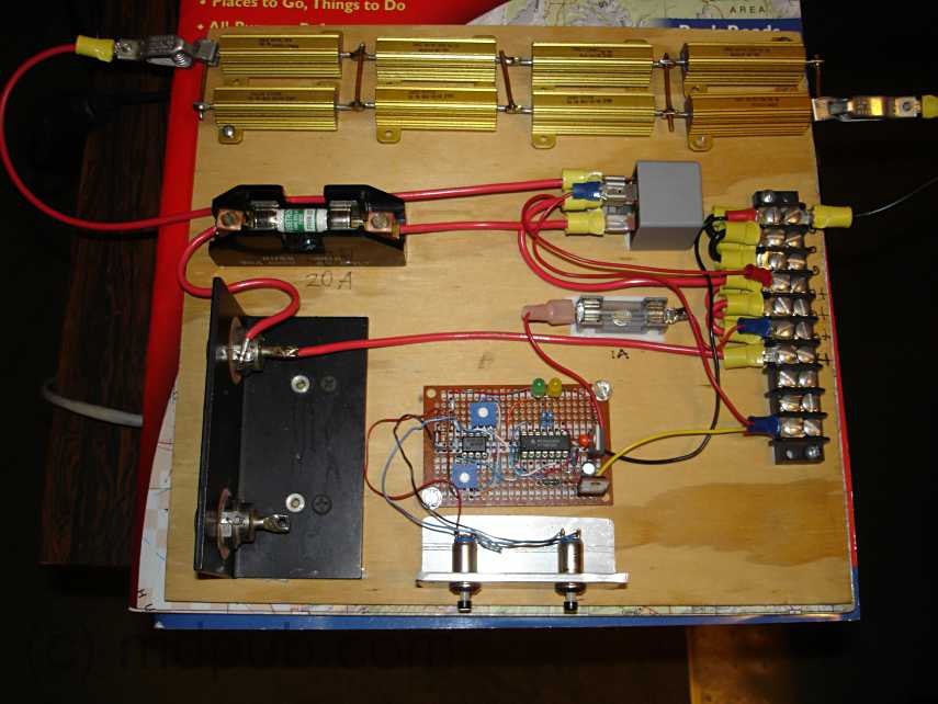
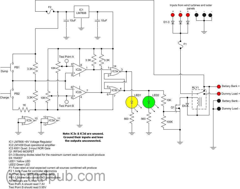
 The first order of business was setting up and bracing the tower. After arriving at my property and unloading my van, I drove to the nearest Home Depot (about 60 miles one way) and bought the 10 foot long piece of 1 1/4 inch conduit I needed for the tower. Once I had it, assembly went quickly. I used nylon rope to anchor the pole to four big wooden stakes driven in the ground. Turnbuckles on the lower ends of each guy-line allowed my to plumb up the tower. By releasing the line from either stake in line with the hinge at the base, I could raise and lower the tower easily. Eventually the nylon line and wooden stakes will be replaced with steel stakes and steel cables. For testing though, this arrangement worked fine.
 This photo shows a closeup of how the guy-lines attach near the top of the tower. I used chain-link fence brackets as tie points for my guy-lines. The fence brackets don’t quite clamp down tightly on the conduit which is smaller in diameter than the fence posts they are normally used with. So there is a steel hose clamp at either end of the stack of brackets to keep them in place.
 This photo shows the base of the tower, staked to the ground, and with the wire from the wind turbine exiting from the Tee below the conduit tower. I used an old orange extension cord with a broken plug to connect between the turbine and the controller. I simply cut both ends off and put on spade lugs. Threading the wire through the tower turned out to be easy. It was a cold morning and the cord was very stiff. I was able to just push it through the length of the conduit tower. on a warmer day I probably would have had to use a fishtape or string line to pull the cord through the conduit. I got lucky.
 This photo shows the turbine head installed on top of the tower. I greased up the pipe on the bottom of the head and slid it into the top of the conduit. It made a great bearing, just as I’d planned. Sometimes I even amaze myself.
 This photo shows the controller, battery and associated electronics all wired up. I have a 120V inverter connected to the battery and a multimeter to keep track of the battery voltage and wind turbine output voltage. Also my electric shaver and battery charger are plugged into the inverter and running off of 120V AC. Later I plugged a long extension cord into the inverter and stretched it back to my camp site. I know this setup is really messy, but I was in a hurry to get up and running to take advantage of the wind once it started blowing. That’s my excuse, and I’m sticking to it.
 This photo is a closeup of the electronics. The meter shows that the wind turbine is producing 13.32 Volts. My electric shaver and battery charger are providing loads on the system through the AC inverter.
 Here the meter shows the turbine producing 13.49 volts. The voltage from the turbine goes up only a little as the wind speed increases once it has a load to power. Once the wind starts blowing, the turbine head snaps around into it and begins spinning up. It spins up quickly until the output voltage exceeds the battery voltage plus the blocking diode drop (around 13.2 volts, depending on the state of the battery charge). it is really running without a load until that point. Once the that voltage is exceeded, the turbine suddenly has a load as it begins dumping power into the battery. Once under load, the rpms only slightly increase as the wind speed increases. More wind means more current into the battery which means more load on the generator. So the system is pretty much self-governing. I saw no signs of over-reving. Of course in storm-force winds, all bets are off. Switching the controller to dump power into the dummy load did a good job of braking the turbine and slowing it way down even in stronger gusts. Actually shorting the turbine output is an even better brake. It brings the turbine to a halt right now, even in strong winds. Shorting the output is how I made the turbine safe to raise and lower, so I wouldn’t get sliced and diced by the spinning blades. Warning though, the whole head assembly can still swing around and crack you hard on the noggin if the wind changes direction while you are working on these things. So be careful out there.
 Eventually I decided my setup was too messy and dangerous. Having high current electrical connections and a rat’s nest of wires on an Aluminum table wasn’t smart. The danger of a spectacular short circuit was too high, so I neatened things up. I set all the electronics on a piece of plywood on top of a plastic storage bin and neatened up the wiring. Then I ran a long extension cord from the inverter back to my camp site and plugged all my stuff into it there.
 Here is a longer view of the complete setup.
 How sweet it is! I have electricity! Here I have my laptop computer set up and plugged into the power provided by the inverter, which in turn is powered by the wind turbine. I normally only have about two hours of battery life on my laptop. So I don’t get to use it much while I’m camping. It comes in handy though for downloading photos out of my camera when its memory card gets full, making notes on projects like this one, working on the next great American novel, or just watching DVD movies. Now I have no battery life problems, at least as long as the wind blows. Besides the laptop, I can also now recharge all my other battery powered equipment like my cell phone, my camera, my electric shaver, my air mattress pump, etc. Life used to get real primitive on previous camping trips when the batteries in all my electronic stuff ran down.
 Here is a photo of me setting up the wind turbine on my remote property during our May 2007 trip to Arizona. I had left most of the equipment on-site in Arizona. I only brought the turbine head and charge controller back home with me. Everything weathered the winter ok. Just some slight surface rust on parts of the tower base. Everything went back together quickly and worked great.
 I used the wind turbine to power my new popup trailer on my spring vacation. The strong spring winds kept the wind turbine spinning all day every day and most of the nights too while I was in Arizona. The turbine provided enough power for the interior 12V lighting and enough 120V AC at the power outlets to keep my battery charger, electric shaver, and mini vacuum cleaner (camping is messy) all charged up and running. My girlfriend complained about it not having enough power to run her blow-dryer though.
 Here my volt meter is showing the turbine producing 14.5 volts in a stiff wind. Although the wind turbine powered the popup fairly well, I think there is room for improvement. I was powering the popup with 120 Volts AC via my inverter. The popup has its own 120V AC to 12V DC power supply for powering the interior lighting and other 12V accessories. The losses involved in converting power to 120V AC and then back to 12V DC probably heavily contributed to the battery running down fairly quickly a couple of times during periods of light wind. Powering the 12V systems directly from the battery would probably work better. The only downside I see is that the DC voltage won’t be regulated and could swing a couple of volts up or down with changes in wind speed. That wouldn’t bother most kinds of lighting too much. Other devices could have a problem with it though.
 This photo shows the turbine spinning away and cranking out the power. I haven’t had the time to complete the rebuild of the charge controller in a weather-proof enclosure. So this time I just put all the electronics in a plastic bin to protect them from the elements. Good thing too, since it rained several times while we were there this time. The jug of lamp oil is on top of the bin to prevent the wind from ripping the lid off.
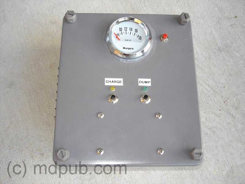

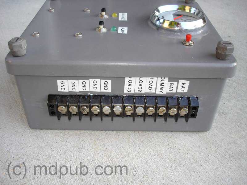
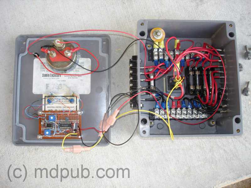
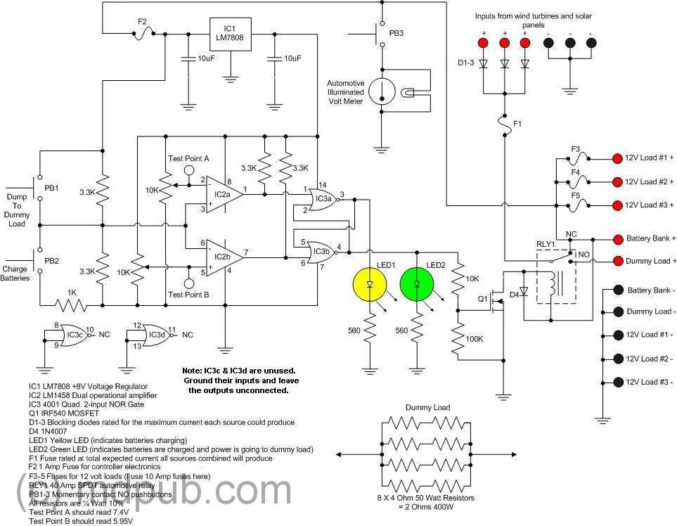
 Jason Markham
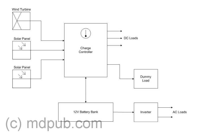
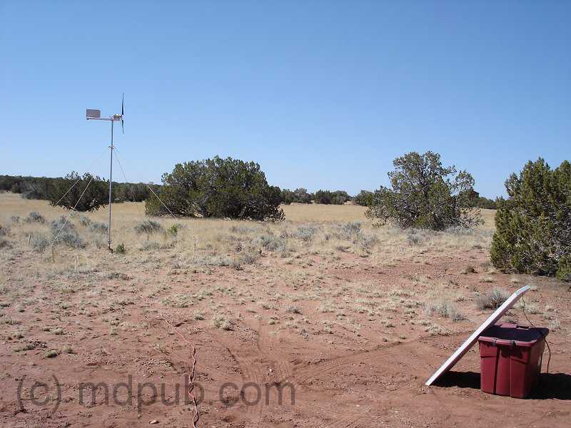
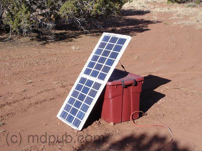

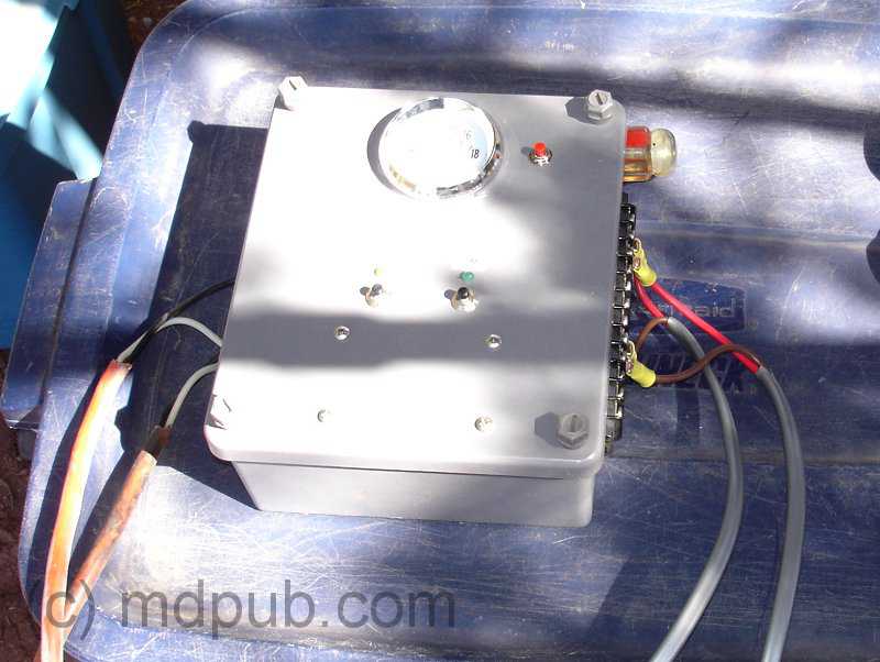
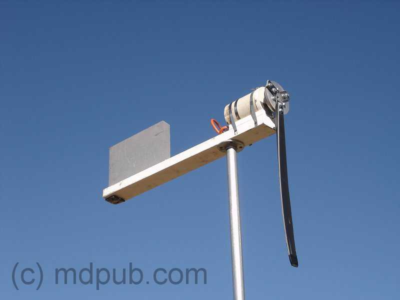
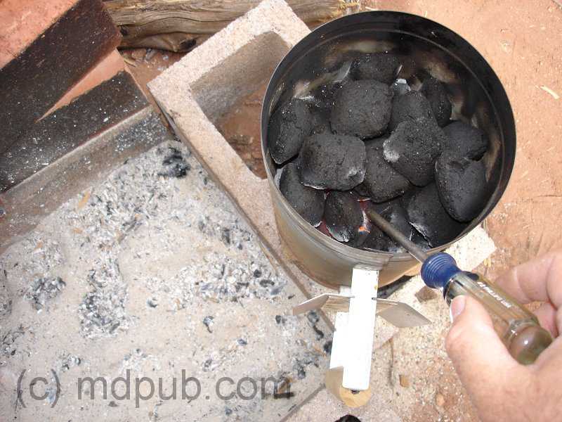
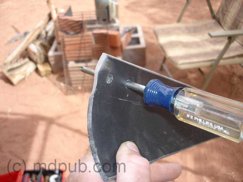
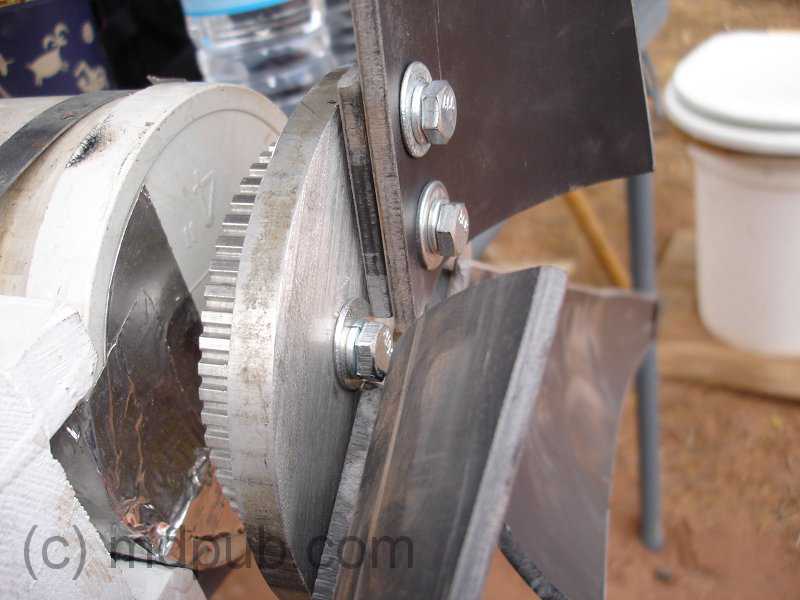
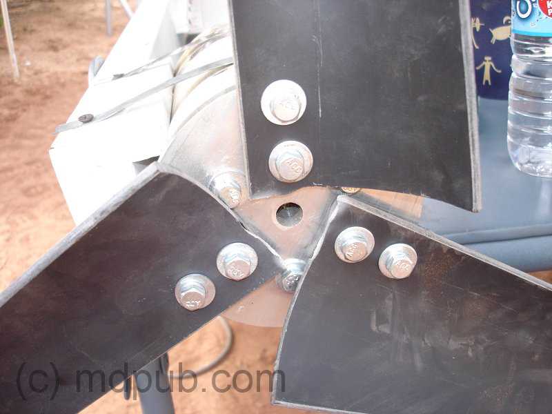
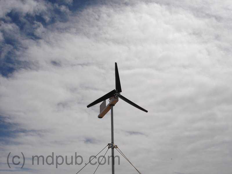


 Several years ago I bought some remote property in Arizona. I am an
  I bought a couple of bricks of 3 X 6 mono-crystalline solar cells. It takes a total of 36 of these type solar cells wired in series to make a panel. Each cell produces about 1/2 Volt. 36 in series would give about 18 volts which would be good for charging 12 volt batteries. (Yes, you really need that high a Voltage to effectively charge 12 Volt batteries) This type of solar cell is as thin as paper and as brittle and fragile as glass. They are very easily damaged. The seller of these solar cells dips stacks of 18 in wax to stabilize them and make it easier to ship them without damaging them. The wax is quite a pain to remove though. If you can, find cells for sale that aren’t dipped in wax. Keep in mind though that they may suffer some more damage in shipping. Notice that these cells have metal tabs on them. You want cells with tabs on them. You are already going to have to do a lot of soldering to build a panel from tabbed solar cells. If you buy cells without tabs, it will at least double the amount of soldering you have to do. So pay extra for tabbed cells.
  I also bought a couple of lots of cells that weren’t dipped in wax from another
  A solar panel is really just a shallow box. So I started out by building myself a shallow box. I made the box shallow so the sides wouldn’t shade the solar cells when the sun comes at an angle from the sides. It is made of 3/8 inch thick plywood with 3/4 X 3/4 pieces of wood around the edges. The pieces are glued and screwed in place. This panel will hold 36 3 X 6 inch solar cells. I decided to make 2 sub-panels of 18 cells each just so make it easier to assemble later. So there is a center divider across the middle of the box. Each sub-panel will fit into one well in the main panel.
 Here is my sort of back of the envelope sketch showing the overall dimensions of the solar panel. All dimensions are in inches (sorry you fans of the metric system). The side pieces are 3/4 by 3/4 and go all the way around the edges of the plywood substrate. also a piece goes across the center to divide the panel into two sub-panels. This is just the way I chose to do it. There is nothing critical about these dimensions, or even the overall design. Feel free to deviate in your own design. These dimensions are included here for those people who always clamor for me to include dimensions on my projects. I always encourage people to experiment and innovate on their own, rather than blindly follow the way I (or anyone else) does things. You may well come up with a better design.
 Here is a close-up showing one half of the main panel. This well will hold one 18 cell sub-panel. Notice the little holes drilled in the edges of the well. This will be the bottom of the panel (it is upside down in the photo, sorry). These are vent holes to keep the air pressure inside the panel equalized with the outside, and to let moisture escape. These holes must be on the bottom of the panel or rain and dew will run inside. There must also be vent holes in the center divider between the two sub panels.
 Next I cut two pieces of masonite peg-board to fit inside the wells. These pieces of peg-board will be the substrates that each sub-panel will be built on. They were cut to be a loose fit in the wells. You don’t have to use peg-board for this. I just happened to have some on hand. Just about any thin, rigid and non-conducting material should work.
 To protect the solar cells from the weather, the panel will have a plexiglass front. Here two pieces of scrap plexiglass have been cut to fit the front of the panel. I didn’t have one piece big enough to do the whole thing. Glass could also be used for this, but glass is fragile. Hail stones and flying debris that would shatter glass will just bounce off the plexi. Now you can start to see what the finished panel will look like.
 Oops! This photo shows a close-up of where the two halves of the plexiglass cover meet over the center divider. I drilled and countersunk holes all around the edges of both pieces of plexiglass so I could screw them onto the face of the panel with 1 inch drywall screws. Be careful working close to the edge of the plexi. If you get to aggressive it will break, as happened here. I just glued the broken piece back in and drilled another hole a short distance away.
 Next I gave all the wooden parts of the panel several coats of paint to protect them from moisture and the weather. The box was painted inside and out. The type of paint and color was scientifically chosen by shaking all the paint cans I had laying around in my garage and choosing the one that felt like it had enough left in it to do the whole job.
 The peg-board pieces were also painted. They got several coats on both sides. Be sure to paint them on both sides or they will curl when exposed to moisture. Curling could damage the solar cells that will be glued to them.
 As I said above, getting the wax off the cells is a real pain. After some trial and error, I came up with a way that works fairly well. Still, I would recommend buying from someone who doesn’t dip their cells in wax. The first step is a bath in hot water to melt the wax and separate the cells from each other. Don’t let the water boil or the bubbles will jostle the cells against each other violently. Also, boiling water may be hot enough to loosen the electrical connections on the cells. I also recommend putting the brick of cells in the water cold, and then slowly heating it up to just below boiling temperature to avoid harsh thermal shocks to the cells. Plastic tongs and spatulas come in handy for teasing the cells apart once the wax melts. Try not to pull too hard on the metal tabs or they may rip off. I found that out the hard way while trying to separate the cells. Good thing I bought extras.
 This photo shows the complete setup I used. My girlfriend asked what I was cooking. Imagine her surprise when I said solar cells. The initial hot water bath for melting the wax is in the right-rear. On the left-front is a bath of hot soapy water. On the right-front is a bath of hot clean water. All the pots are at just below boiling temperature. The sequence I used was to melt the bricks apart in the hot water bath on the right-rear. I’d tease the cells apart and transfer them one at a time to the soapy water bath on the left-front to remove any wax on the cell. Then the cell would be given a rinse in the hot clean water on the right-front. The cells would then be set out to dry on a towel. You should change the water frequently in the soapy and rinse water baths. Don’t pour the water down the sink though, because the wax will solidify in your drains and clog them up. Dump the water outside. This process removed almost all the wax from the cells. There is still a very light film on some of the cells, but it doesn’t seem to interfere with soldering or the working of the cells. A solvent bath would probably remove the rest of the wax, but that would be dangerous and stinky since the only solvents I could think of that would cut wax are either flamable, toxic or smelly, or all three.
 Here are some separated and cleaned solar cells drying on a towel. Once separated from their wax stabilized brick form, they are amazingly fragile and difficult to handle and store. I would recommend leaving them as bricks until you are ready to install them in your panel. That way you won’t wreck them before you get to use them. So build the panel first. Now it’s time to start installing them in the panel
 I started out by drawing a grid pattern on each of the two pieces of pegboard, lightly in pencil, so I would know where each of the 18 cells on them would be located. Then I laid out the cells on that grid pattern upside-down so I could solder them together. All 18 cells on each half panel need to be soldered together in series, then both half panels need to be connected in series to get the desired voltage.
 I used a low-Wattage soldering iron and fine rosen-core solder. I also used a rosen pen on the solder points on the back of the cells before soldering. Use a real light touch with the soldering iron. The cells are thin and delicate. If you push too hard, you will break the cells. I got careless a couple of times and scrapped a couple of cells.
 I repeated the above steps and soldered solar cells together until I had a string of six cells. I soldered tabs from scrapped cells to the solder points on the back of the last cell in the string of six. Then I repeated the whole process two more times to get three strings of six cells for a total of 18 for this half of the panel.
 Gluing the cells in place proved to be a little tricky. I placed a small blob of clear silicone caulk in the center of each cell in a six cell string. Then I flipped the string over and set in place on the pencil line grid I had laid out earlier. I pressed lightly in the center of each cell to get it to stick to the pegboard panel. Flipping the floppy string of cells is tricky. Another set of hands may be useful in during this step.
 Next time I will do it differently. I will solder tabs onto the backs of all the solar cells. Then I will glue all the cells down in their proper places. Then I will solder the tabs together. It seems like the obvious way to go to me now, but I had to do it the hard way once to figure it out.
 Here I used copper braid to interconnect first and second strings of cells. You could use solar cell tabbing material or even regular wire. I just happened to have the braid on hand. There is another similar interconnection between the second and third strings at the opposite end of the board. I used blobs of silicone caulk to anchor the braid and prevent it from flopping around.
 Here I am testing first half panel outside in the sun. In weak sun through clouds the half panel is producing 9.31 Volts. YAHOO! It works! Now all I had to do is build another one just like it.
 Each of the half panels dropped right into their places in the main panel frame. I used four small screws (like the silver one in the photo) to anchor each of the half panels in place.
 Wires to connect the two half panels together were run through the vent holes in the central divider. Again, blobs of silicone caulk were used to anchor the wire in place and prevent it from flopping around.
 Each solar panel in a solar power system needs a blocking diode in series with it to prevent the panel from discharging your batteries at night or during cloudy weather. I used a Schottky diode with a 3.3 Amp current rating. Schottky diodes have a much lower forward voltage drop than ordinary rectifier diodes, so less power is wasted. Every Watt counts. I got a package of 25 31DQ03 Schottky diodes on
  I drilled a hole in the back of the panel near the top for the wires to exit. I put a knot in the wires for strain relief, and anchored them in place with yet more of the silicone caulk.
 And still more silicone caulk was used to seal the outside of the panel where the wires exit.
 I added a polarized two-pin jones plug to the end of the panel wires. A mating female plug will be wired into the charge controller I use with my
 UPDATE: 10/12/09
 Here I am testing the Voltage output of the completed panel in bright winter sunlight. My meter says 18.88 Volts with no load. That’s exactly what I was aiming for.
 Here I am testing the current capacity of the panel, again in bright winter sunlight. My meter says 3.05 Amps short circuit current. That is right about what the cells are rated for. So the panel is working very well.